
-----
Anode to Cathode Ratio, Size, Spacing, Placement in Anodizing
adv.
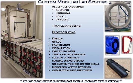
for Shops, Specifiers & Engineers
avail from eBay, AbeBooks, or Amazon

avail from eBay, AbeBooks, or Amazon
avail from eBay, AbeBooks, or Amazon
avail from eBay, AbeBooks, or Amazon
avail from eBay or Amazon
(as an Amazon Associate & eBay Partner, we earn from qualifying purchases)
[editor appended this entry to this thread which already addresses it in lieu of spawning a duplicative thread]
Q. Hello,
My name is Katerina and I work as a manufacturing engineer for a fabrication company. I am working on implementing an anodizing line internally and I have an insane amount of questions regarding the anode-to-cathode ratios, especially with the 3-to-1 ratio.
We are not a custom shop and due to the geometries of the parts, I have a lot of varying total surface area for each batch that needs to go into the anodizing tank. I am also confined within the limits of the tank and cannot set each batch to the same total surface area or I would be reducing the total number of parts in each bath.
Do I need to really bring the total surface area of the cathodes to fractions? Can I round the the nearest whole cathode? I don't know if these questions sound stupid but if my total surface area is only 14.52 sq ft and my cathode surface area is 1.1438 sq ft, do I really need to shield 3/4 of a cathode since ideally the number of cathodes I need in the tank is 4.23.
- Sparks, Nevada
February 1, 2024
A. Hi Katerina,
If I am understanding you, you expect your work load to be around 14.52 sq. ft, so if you target a 3:1 anode to cathode ratio, you'd like to have about 4.84 sq. ft. of cathode area. But since your cathodes are 1.1438 sq. ft. each, that would be about 4.23 cathodes.
4 cathodes would be ideal, but 3 would be fine too -- it's simply not a critical issue at all. :-)
Luck & Regards,

Ted Mooney, P.E. RET
Striving to live Aloha
finishing.com - Pine Beach, New Jersey
Ted can be retained for immediate
answers or long term project help
Q. Hey Ted,
Thanks for getting back to me. I am happy to know that the ratio has a little wiggle room but do wonder how much this will effect my 720 rule or if this will directly effect my times? I have not seen any information out there regarding how the ratio relates back into my 720 equations. Would being slightly under in cathodes result in more processing time?
Additionally, we are not a custom shop, we are only anodizing our own parts for assembly. We previously had an anodize system that was ancient but had nice titanium racks that I am reusing while we design more. This has made all of my batch sizes immensely different in surface area (luckily don't have to include the surface area of the rack since they're titanium or I would be in a real pickle). The rectifier that was purchased only has 500 amps so I am really limited on how many parts I can get. In an attempt to maximize the number of parts while maintaining the limitations of the system, I have batches that require only 2 cathodes while other that need 6. I understand that I need to shield these cathodes between batches but hesitate to make operators reach over the sulfuric tank to get them on (It's a tight space). I was wondering if anyone had experience in custom anodize shops with changing out cathodes or shielding them? Or should I bite the bullet and reduce the number of parts in my largest surface area batches?
Thanks in advance for your help, I was very excited to see you reply to my question since I have been reading through this forum fairly heavily the last few days, you are a little celebrity on here. :)
- Sparks, Nevada
February 2, 2024
A. Hi again K.,
The cathode size will have no effect on the 720 Rule ... which is simply a specific case of Faraday's Law with constants specific to anodizing inserted into his law.
Don't fret over the cathode area, just put in 4 and forget the removal & shielding. Ideal cathode size has nothing to do with the one individual load, but rather it has to do with optimizing a long-term equilibrium issue. We'll see what other readers say but I have personally never even heard of adding & removing cathodes for different load sizes. Run as many parts as can fit and not exceed your rectifier capacity.
As for 'celebrity', I'm the blabbermouth because I'm the operator of the forum, so naturally I don't like to see unanswered questions :-)
adv.
If you decide to retain personalized help, Robert Probert and Drew Nosti are supporting advertisers who are experts in anodizing.
Luck & Regards,
Ted Mooney, P.E. RET
Striving to live Aloha
finishing.com - Pine Beach, New Jersey
Ted can be retained for immediate
answers or long term project help
A. The ratio of the anode to the cathode of 3:1 is a guideline not an absolute. In a perfect world it would be great to always have the 3:1 ration, but in most if not all anodizing it is not practical to hold that ratio. Trust me, I have customers who are using 3:1 and some who use 1:3. From my perspective, having cathodes evenly spaced in your tank will be more important than trying to hold the 3:1 ratio.

Drew Nosti, CEF
Anodize USA
Ladson, South Carolina

February 12, 2024
⇩ Related postings, oldest first ⇩
Q. WHAT IS THE MINIMUM AND MAXIMUM DISTANCE BETWEEN THE ANODE AND CATHODE IN CHROMIC ANODIZE PROCESS?
THE DIMENSIONS OF THE ANODIZE TANK : 36 INCH WIDTH, 50 FOOT LENGTH AND 10 FOOT DEEP.
IS THERE A RELATION BETWEEN THIS DISTANCE AND A VALUE OF CURRENT. ANY HELP WOULD BE APPRECIATED. THANKS.
NMF Canada - Montreal, Canada
1999

Schematic of a Haring Cell
Source: www.pfonline.com/articles/an-investigation-of-the-effect-of-nile-blue-on-the-electrodeposition-of-nickel-on-brass-from-a-watts-type-bath
Remember that the solution has resistance (although chromic acid is fortunately very conductive). You can measure the resistivity of the solution with a Haring cell.
but for a first cut, say it's about 4 ohm-cm.

The resistance of the solution is the resistivity x length / cross sectional area. So if the anode-cathode spacing is 18 inches, or 45.72 cm, then the solution resistance you will encounter in anodizing a square foot of work is 4 ohm-cm x 45.72 cm / 929 cm2, or 0.197 ohms.
So if you anodize at 12 ASF, then according to Ohm's Law the voltage drop across the solution will be 2.4 volts. This is approximate, and it's actually somewhat lower because the current doesn't follow only the horizontal straight lines ⇨

Ted Mooney, P.E.
Striving to live Aloha
finishing.com - Pine Beach, New Jersey
Ted can be retained for immediate
answers or long term project help
Q. For type II anodizing are there any problems associated with running an anode/cathode ratio much smaller than 3:1, say 1:5? Like if you did a small run in a large anodizing tank.
Michael Peppard- Detroit, Michigan, USA
2001
A. By type II I hope you mean sulfuric anodise. If you do there is no problem - I ran some jobs for home in the big tank total anode area approx. 16 inches square and the cathode area 36 square foot a ratio of 1 to 324 and the jobs came out fine.

Martin Trigg-Hogarth
surface treatment shop - Stroud, Glos, England
Multiple threads merged: please forgive chronology errors and repetition 🙂
Q. How critical is cathode placement in a type II anodizing tank? I realize cathode area is important, load type, shape of parts to be anodized, etc. Is it better to have one cathode running the full length of the tank and up both ends? or two on the sides only? what is the optimum setup generally speaking?.
Thanks,
anodizer - Nelson, New Zealand
2005
A. Cathodes for anodizing -- a subject near and dear to my heart and wallet. Cathodes should be aluminum, 6063 T6, and set up on both walls of the tank with the parts centered as best as possible between them. A ratio of 3 to 1 is best (3 Sq Ft anode, 1 Sq Ft cathode) or as close as possible, understanding a job shop environment. Cathodes should not extend below the parts in the tank (again remember the job shop variables). Bolting is recommended over welding if you follow good judgment in adequate contact surface area and torque. Never put joints below or close to solution level. Use a conductive sealant.
Drew Nosti, CEF
Anodize USA
Ladson, South Carolina
A. From the anodizing job shop side of things (as installing excess cathodes would unnecessarily lighten MY WALLET), 3:1 anode to cathode is a bit extreme and I've read in various text books that this can be as high as 10:1. The only difficulty comes in guessing the anode area on that next job coming in -- if you are indeed a job shop, that's always a crap shoot. In that case, I'd go with 7:1 (Come on 7's) ... good luck, don't crap out!

Milt Stevenson, Jr.
Plating shop technical manager - Syracuse, New York
Multiple threads merged: please forgive chronology errors and repetition 🙂
Q. Hey gang ... I have some questions which directly relate to the cathodes used in type II anodizing. They are as follows:
1. Using 6061/6063 aluminum sheeting versus lead sheeting -- what are the pros and cons?
2. I understand that the cathode:anode ratio should be around 3:1. How critical is this? Can a person utilize a much greater ratio, for example 30:1? What might the result be?
3. I realize it is common practice to remove the cathode(s) from the tank when not in use but I am curious what the cons are to leaving the cathode(s) in the tank full time.
4. When calculating the surface area of a sheet of aluminum which is resting flat against the wall of a tank (or very close to the wall), does one consider both sides of the sheet in the calculation or just the side facing inward to the tank?
The reason I ask these questions is because I am currently building an anodizing tank. Using 1/2" polypropylene, I have welded up a box with internal dimensions as follows : 30"L x 14"W x 19"H. I was thinking of using 1/16" aluminum sheeting as the cathodes and basically line the inside of the tank. My thoughts were to leave this aluminum in the tank full time.My thanks goes out to all who reply. Cheers!

Daniel DeGueldre
anodizing shop entrepreneur - Ste. Anne, Manitoba, Canada
2005
A. Aluminum is more conductive, takes less watts, saves on cooling. Lead puts some lead into the waste stream. Purists say use 6063T5, but just recently a shop (who claims no stray current or galvanic current) got less than 6 months. Another shop that I set up got 4 years out of 6061 1/8 inch thick! For type II the ratio is NOT critical, but 30 to 1 may be a problem. Do not do it.
If you are talking a lead lined tank, then use plastic to mask the bottom and ends. My client that got 4 years with 6061 -- NEVER removed the cathodes. There was no stray current. The heat exchanger was outside. Use one side facing the work.Wow, 1/16 might be a bit thin. But do not line the tank. Have no cathode on the bottom and no cathode on the ends.

Robert H Probert
Robert H Probert Technical Services
Garner, North Carolina

A. The use of lead in the form of sheet or tubing is both more expensive and less efficient than aluminum. To avoid the aluminum dissolving readily in the anodizing bath the use of 6063T6 is mandatory. It is not necessary to remove them when not anodizing. Try to stay as close to a 3 to 1 ratio (3 anode to 1 cathode sq. ft.). If you have more questions I would be glad to help.
Drew Nosti CEF
AESF Light Metal Committee
Member AAC
Drew Nosti, CEF
Anodize USA
Ladson, South Carolina
Q. Thank you for the input. Drew, you posted that the anode-to-cathode ratio is to be in the range of 3:1. That is to say that for every 3 sq. ft of anode, 1 sq. ft. of cathode is required. I have been led to believe the opposite is true and that for every 1 sq. ft. of anode, 3 sq. ft. of cathode is to be utilized. Perhaps my research is incorrect. Please verify. I appreciate the help and conclude that: 6063T6, 1/8" thick sheeting will be utilized as cathodes. The sheeting will be fabricated to hang over the sides of the tank in multiple sections thus allowing cathode size manipulation. The cathodes will be removed when not in use, rinsed and hung to dry. Now is the anode-to-cathode ratio 3:1 or 1:3? Thanks all ... Cheers!
Daniel DeGueldre
anodizing shop entrepreneur - Ste. Anne, Manitoba, Canada
2005
A. To answer my own question - a rather basic one I might add. While visiting Mr. Nosti's website I have concluded that the anode:cathode ratio is 3:1. I hope you do not mind Mr. Nosti, I have taken this quote from the AnodizeUSA [a finishing.com supporting advertiser] website, "...the ratio of 3 sq feet of anode to 1 sq foot of cathode gave the most consistent anodizing.". It should be noted that Mr. Nosti is referring to 6063T6 aluminum cathodes. It's funny to think, how we grow we sometimes misunderstand stuff. in fact, I feel quite foolish at the moment. For 6 months now I was under the impression that the anode:cathode ratio was to be 1:3. I was anodizing with decent results utilizing this method. I was also using just simply 1/16 aluminum sheeting of an unknown alloy for cathode material. I have currently reversed that theory thanks to Mr. Nosti and finishing.com. My current setup will soon be recalibrated implementing a 3:1 (anode:cathode) ratio while utilizing 6063T6 aluminum cathodes. Just one more step in the right direction. Thanks people! Cheers!
Daniel DeGueldre
anodizing shop entrepreneur - Ste. Anne, Manitoba, Canada
2005
Ed. note: What gets everyone so easily confused, including me of course, is that in electroplating the parts you are plating comprise the cathode, and the anodes are the stationary baskets full of metal chunks. In anodizing the parts you are anodizing are the anodes, and the permanent lead or aluminum bars are the cathodes :-)
![]() Thanks Dan, it is nice to hear that correct information is spreading. Remember it is not a perfect world and in anodizing you can get almost anything to "WORK" .The question is what is the best way. When starting or updating any metal finishing line try to travel in a direction that will lead to the best technology, even if it is in small steps. Good luck.
Thanks Dan, it is nice to hear that correct information is spreading. Remember it is not a perfect world and in anodizing you can get almost anything to "WORK" .The question is what is the best way. When starting or updating any metal finishing line try to travel in a direction that will lead to the best technology, even if it is in small steps. Good luck.
Drew Nosti, CEF
Anodize USA
Ladson, South Carolina
A. We have had a member on another anodizing forum try this unusual (to us anyway) 1:3 cathode/anode area. There is definitely something useful here, we will check this out in detail with properly instrumented anodizing experiments this spring and inform Drew directly of our findings.
Paul Yursis [deceased]- Columbia, Maryland, USA
Ed. note: it is our sad duty to advise of the passing of Paul Yursis in August 2005.
Here is a brief obituary by Mike Caswell.
A. Hello, the ratio from anode:cathode is 3:1 as a minimal ratio in the project of a tank building for a full charge, maximal anode area or rectifier capability that define the greatest area that can be processed.
If you use in any given moment a 30:1 ratio, no problem; make sure that the rectifier is so adjusted to prevent burning, in the ratio ASF (amp per sq. ft.) that you use conform your bath and Tank construction condition.
I do not remove the cathodes from the Tank, only for cleaning or replacing.
- Blumenau, Santa Catarina, Brazil
Q. The anode to cathode calculation is 3:1, this is for maximum load size of the parts? Since once we install the cathode of a size then we cannot change for each and every batch.
Aijazullah Tajir- Abu Dhabi, UAE
February 4, 2013
Q. Hi everyone,
I have a quick question regarding the 3:1 anode to cathode ratio required for anodising. Is it necessary to be able to maintain this ratio by having the cathode in sections, or can quality results still be achieved by sizing the cathode for the maximum capacity?
Thanks for your help!
- Coleraine, Northern Ireland
September 17, 2013
A. Just size for the maximum surface area load using separate cathodes and not using the whole tank for a cathode. Area ratio is not as important on regular anodizing up to 0.0008 inch, however, more critical in hardcoat.
Robert H Probert
Robert H Probert Technical Services
Garner, North Carolina
A. Dear Sir,
First of all we need to define the size of anode. I have experienced that undersize anode will definitely heat up at the junction point. It results in loss of energy in form of heat dissipation.
So if you plan to give suppose 2000 amps DC current then the anode bus bar size should be minimum 100 mm width and 20 mm thickness. That is 100* 20 =2000 or you can use 80 mm width and 25 mm thickness. Again the calculation will come up to 2000.
So you can use different sizes with result amounting to 2000 for 2000 amps DC current.
Actually I am using 1:3 anode to cathode ratio. I am still confused whether it's right or wrong. But I am getting consistent anodizing.
Cheers!!
Happy Anodizing.
- Ahmednagar, Maharashtra, India
Q. Dear friends,
How to estimate the maximum surface area of parts that can be processed with respect to cathode and tank size?
- Abu Dhabi, UAE
January 30, 2014
Q1. What is the effect of more or less (than the standard 3:1 ratio) anode:cathode ratio on the quality & quantity of anodic coating?
Q2. How can we decide proper current density, required for type II anodising, with respect to the sulfuric acid and aluminium contents and the temperature of anodising bath?
Q3. How to restrict the solidification of caustic sludge in caustic etch bath used for etching of aluminum?
Service in Electroplating Industry - Nagpur, Maharashtra, India
August 10, 2014
Aluminum How-To
"Chromating - Anodizing - Hardcoating"
by Robert Probert
Also available in Spanish
You'll love this book. Finishing.com has sold almost a thousand copies without a single return request :-)
Hi cousin Rajabhau ...
A1. The 3:1 anode to cathode ratio is simply widely used and has been found not to introduce problems with dissolved aluminum concentration or overheated cathodes, while allowing the size of the load (anode area) to vary widely. It's a target to plan for at the design stage rather than something to worry about day to day.
A2. Although some guidelines are based on first principles (like the '720 rule' which was born from Faraday's Law, and the 50:50 rule which stems from the way aluminum combines with oxygen), much of our anodizing knowledge is empirical (certain operating parameters have been found to work better than others). There have been limited attempts to chart how you should try to compensate some of the other parameters if you choose not to adhere to the empirically determined guidelines for some of them, and Robert Probert's "Aluminum How-To" discusses the issue, but I don't think compensation is an ideal approach.
Production floor electrochemistry is complicated, and I think the best advice is from Larry Durney's "Trouble in Your Tank?": Obey the Letter of the Law. Look up the recommended voltage for the alloy in question, so you have it (14.5 V for 5052 through 23 V for 319 & 380) and then anodize at 12 ASF, 15% by weight H2SO4, less than 0.02% Cl, at 70 °F.
A3. If you put "aluminum etch sludge" into the Google custom search engine near the top of our pages you will see several interesting discussions on the topic. It is claimed that gluconate is a valuable addition agent for this, but keeping the solution moving until it can be filtered can also be important. Please continue the sludge topic on one of those threads. Good luck.
Regards,
Ted Mooney, P.E.
Striving to live Aloha
finishing.com - Pine Beach, New Jersey
Ted can be retained for immediate
answers or long term project help
We purchased a hobby anodizing kit, using 7 gallon buckets. My question is on setting up the anodizing anode and cathode.
I'm using a titanium bus bar and 8" x 8" lead cathode, and supporting the parts with titanium wire that came with the kit. Doing several trial runs with aluminum (6061), I'm not seeing much in voltage increasing by the end of process.
Q1. Would it be better to use 6063 aluminum 1/8 rod to support the parts from the bus bar?
Q2. I'm using the 720 rule calculator and 4.5 current density (found an app on iPhone):
34 sq in, .8 mil, 4.5 A/sq ft, set current to 1.06 A for 128 minutes. I have a 15 VDC power supply. Should I be seeing the voltage increase as the resistance of the part increases? If so, should it be a lot or a little.
Q3. Next, would using the hot seal method for clear coat be better than the nickel-acetate sealant that comes with the kit?
We normally have parts farmed out but are using it when we have time constraint.
- Syracuse, New York U.S.A
October 4, 2014
Thank you to all the responders!
Readers: Now it's your turn. Please help us build a shockingly good forum.
Hi Mark. We offer technical comments in this forum but we don't judge the pluses & minuses of particular brands or suppliers. But there is a borderline issue here in that you are using a hobby priced system and many of us would not consider hobby components adequate for industrial anodizing. This system apparently uses a technique called "low current density anodizing", which is not to my knowledge endorsed in the industrial sector: You are anodizing at 4.5 ASF whereas most anodizers would use 12 to 18 ASF. So yes, it takes 3 times as long.
A1. I think the titanium wire is a better approach because the aluminum rod will become anodized and can't be used again until it is stripped. The wire must be large enough to carry 1.06 Amps; the conductivity of titanium is only a small fraction of copper, so we're talking substantial wire, not thread.
A2. The voltage should increase substantially; if it's not building to 12 volts, neither is the anodizing. I suspect you have poor connections somewhere. Note that 0.8 mils is a very substantial thickness, exceeding the standards for architectural anodizing. Most people would not anodize to that thickness unless they are doing black, where greater thickness means more dye for greater color saturation -- and if I read correctly, you are doing clear. Most specs would call for more like 0.2 or 0.3 mils for clear anodizing ... where did you get this spec and/or what is the function of these anodized parts?
A3. Nickel acetate sealing is fine, but so is hot water sealing. Hot water would leave you with fewer variables to tame. Good luck.
Regards,
Ted Mooney, P.E.
Striving to live Aloha
finishing.com - Pine Beach, New Jersey
Ted can be retained for immediate
answers or long term project help
combo magnetic & eddy-current coating thickness tester
on eBay or Amazon
(affil link)
Q. Thank you for replying so quickly.
All connections have been checked with the exception of using SS bolts for connecting to the lead cathodes and titanium bus bar anode. My suspect was the small gauge wire being used to support the part. Yes I know it is not the industry way but if it works in a pinch with the same results when on a time constraint we have no problem with it. I wasn't sure on the mil size when I did the calculation. I since know the parts that we have professionally done is .4 mil. We did purchase a handheld device for checking the anodize thickness. The parts are used in an inspection device for the Pharma Industry. I will see about getting a heavier gauge titanium wire; if not we can strip the aluminum. Only a couple parts are being done monthly.
In regards to the hot seal will it hold up just as well compared to the nickel acetate? Again thank you for all and any future help.
Mark Atkinson [returning]- Syracuse, New York
A. Hi again. Supposedly, medium temperature proprietary nickel acetate seals offer somewhat better corrosion resistance than hot water. But proprietary products always have a champion and hot water will never have one; so the difference, if any, will probably be much less than what those champions tell you -- my bet is it won't be significant at all. Where nickel acetate sealing gets more important is in color anodizing.
Regards,
Ted Mooney, P.E.
Striving to live Aloha
finishing.com - Pine Beach, New Jersey
Ted can be retained for immediate
answers or long term project help
A. I think for your application I would change several things:
1. Use an aluminum buss bar
2. Use aluminum cathodes (6063 is preferred)
3. Use Aluminum welding rod as your method of contact to your part, it's relatively inexpensive, readily available in 1/8" diameter, and carries current much better than Ti wire. I like 1100 series rod, as it bends easily w/o breaking...however 4043, and 5356 will also work. When you're done with the wire, just toss it and recycle it. I wouldn't hassle with the stripping.
4. You didn't mention the amperage output of your rectifier, but as Ted mentioned, 4.5 ASF is pretty low. Using 12-15 ASF, you should be able to achieve your desired .0005" coating thickness in approx. 25 minutes.
5. Your mid temp Ni acetate seal sounds just fine for your application, however I will disagree with Ted in that a high temp (200-212 °F) DI seal offers better corrosion resistance, but it doesn't seem practical in your situation.
Finally, a side note. You need to realize that since your anodizing process appears to be being used in a commercial application, you are probably subject to local and federal environmental laws, and may need the appropriate permits. These permits, the monitoring equipment, and the lab testing of your effluent is not inexpensive...and you may find that it might be better to pay a little OT to your employees in order to get the job completed/manufactured early so that you can use your outsource anodizer, and not miss your shipping deadline to your customer. The fines for not abiding by environmental laws can be extremely high.

Marc Green
anodizer - Boise, Idaho
October 5, 2014
Q. I have a basic understanding of most of this; however, could someone please tell me what is the correct explanation of:
Which is the anode and which is the cathode. Is the anode attached to the part being anodized and is it attached to the negative lead or do I have it all mixed around. Many thanks.
Bill
- Foley, Alabama - USA
February 16, 2015
A. Hi William. In metal finishing, the positive pole is the anode, the negative pole is the cathode. As you may know, in computer programming a "+" sign is sometimes used to represent the word "and"; so a memory aid I use is to mentally call the positive pole the "andode" and the negative pole the "can'tthode :-)
In anodizing, the part being anodized is made anodic (connected to the positive lead of the power supply). In electroplating the part being plated is made cathodic or negative. For this reason, when you are talking about electroplating, you connect the positive lead to "anodes" made of copper, or zinc, or nickel (or another metal) as the source of the metal; but in anodizing you connect the negative lead to aluminum or lead "cathodes".
No metal is deposited in anodizing. Rather, oxygen is drawn to the anodically charged parts and converts the aluminum on the surface of the part to oxides/hydroxides of aluminum. Good luck.
Regards,
Ted Mooney, P.E.
Striving to live Aloha
finishing.com - Pine Beach, New Jersey
Ted can be retained for immediate
answers or long term project help
![]() Thanks Ted
Thanks Ted
- Foley, Alabama - USA
February 17, 2015
Q. I was led to believe that the Anode (parts being anodized) was 1 to 3 (cathode - negative plate). There is some conflicting information here ... (and elsewhere :))
Dan Orcutt- Siloam Springs, Arkansas USA!
May 30, 2015
A. Hi Dan. Although metal finishing is a science, a lot of it is empirical knowledge rather than based on first principles of mathematics. Furthermore, some of the advice has to do with secondary effects in production situations rather than whether or not you can successfully electroplate or anodize on a one-time basis. For example, in nickel plating you might polarize a nickel anode if it is too small, or in zinc plating you might have to fight against rising solution concentration if you have too much zinc anode area.
For decades it was traditional to line anodizing tanks with lead as a corrosion-proof lining, then simply connect the negative lead to the lining, making the entire area of the tank the cathode. This probably resulted in anode to cathode ratios of 1:5 to 1:50 and yet the process survived; so I doubt that slightly too much cathode area is a serious problem in anodizing. Too little might cause over-heating, or perhaps excessive corrosion of the cathode, or perhaps limit the speed of the process due to not being able to get enough hydrogen through the boundary layer of a very small cathode, but I think the issue is not critical and it will not be valuable to try to prove wrong those who think a 3:1 anode to cathode ratio is the ideal -- it's a good target if there's no good reason why not, but I doubt that 2:1 would cause any problems.
For the very simplest answer of all, go with a 1:1 -- and you'll never have to worry again about which way is which :-)
Regards,
Ted Mooney, P.E. RET
Striving to live Aloha
finishing.com - Pine Beach, New Jersey
Ted can be retained for immediate
answers or long term project help
Anode to Cathode Ratio for Type III Anodizing
Q. I have been experimenting with the anode to cathode ratio in our anodizing line. I'm currently at the 3 to 1 ratio for 55 sq ft. Is there a benefit to add more cathode if the tank size and solution flow allow it?
Scott FrazierAnodizing Manager - Spokane Valley, Washington USA
January 28, 2016
A. Hi Scott. Those who feel that a carefully controlled anode-to-cathode ratio is important tend to favor the 3 to 1 ratio that you believe you have. So I would not change it.
Regards,
Ted Mooney, P.E. RET
Striving to live Aloha
finishing.com - Pine Beach, New Jersey
Ted can be retained for immediate
answers or long term project help
January 2016
A. Honestly I have seen ratios of cathodes all over the place. The 3:1 ratio is a starting point, I use it to do calculations for a set up. Since most anodizing lines see many different SQ FT of work, it is impossible to keep this ratio constant. So guys think of the 3:1 ratio as flexible and use what you need to get great work. I am though a strong believer in 6063T6 and have documentation/studies to confirm it.
Drew Nosti, CEF
Anodize USA
Ladson, South Carolina
August 5, 2016
⇦ Tip: Readers want to learn from your situation;
so some readers skip abstract questions.
Q. Hello, Can someone spell about the effect of rack surface area on work out of Cathode area?
Khushal Rane- Jalgaon, Maharashtra
May 17, 2018
? Hi Khushal. I think you're asking about anode-to-cathode ratio, but the somewhat different rhythm of Indian English compared to United States English leaves me unsure.
Please introduce your own situation rather than trying to cast the question in the abstract, and I think we'll be able to communicate better. Thanks!
But in the meanwhile, anode to cathode ratio is not nearly as important as many others parameters, so don't let it steal your focus :-)
Regards,
Ted Mooney, P.E. RET
Striving to live Aloha
finishing.com - Pine Beach, New Jersey
Ted can be retained for immediate
answers or long term project help
Q, A, or Comment on THIS thread -or- Start a NEW Thread