-----
How to calculate anodizing time for different load sizes
Q. I'm a newly graduated student; I am training now in an aluminum factory using 6063 alloy for anodizing and electroplating. I want the main calculations and formula requirement to help me to reach to 25 micron [0.0001"] ^0.001" thickness. The bath size is 7.5 * 1.5 * 3 m, the rectifier is 24V, I work with a temperature of 18-22 °C and I use Cu bussing.

mohammed alzwey
chemical engineering - bengahazi, libya
August 19, 2023
Ed. note -- Editor's error: Mr. Alzwey wrote '25 micron', but we made a typo when providing English units, which we fixed after Mr. Rochester's posting.

Aluminum How-To
"Chromating - Anodizing - Hardcoating"
by Robert Probert
Also available in Spanish
You'll love this book. Finishing.com has sold almost a thousand copies without a single return request :-)
A. Hi Mohammed. The calculations & formula themselves are pretty simple. The size of the tank doesn't enter into the calculations directly, rather you need about 1.2-1.5 A/dm2 of surface area of the components [12 ASF] as previously mentioned on this page, and a little over an hour of anodizing time. For the chemical formula, you use approx. 15% by weight / 10% by volume sulfuric acid.
But successful anodizing is not drop dead easy, it's not simply a matter of putting the components into 15% sulfuric acid at that time & temperature for an hour or so. And the thickness you are aiming for is at the extreme top end of what is do-able with Type II anodizing, because the resistance of the anodizing gets higher at greater thicknesses as does its dissolution rate by the sulfuric acid. At this thickness you may be entering quasi "hard coat" range where you might need higher voltage, lower temperature, and/or additives. Good luck!
Regards,

Ted Mooney, P.E. RET
Striving to live Aloha
finishing.com - Pine Beach, New Jersey
Ted is available for quick help
or longer-term assistance.
A. 0.0001 inches is 2.54 microns (micrometers).

Tom Rochester
CTO - Jackson, Michigan, USA
Plating Systems & Technologies, Inc.
August 21, 2023
⇩ Related postings, oldest first ⇩
Q. How could I determine the processing time for different load size with regards to Current and/or Voltage? e.g., A load size of 35 sq m to process in sulfuric acid solution (195-205 g/l) to 12 micron and the rectifier capacity is 5000 Amps with a Voltage output of 22 V.
Pelimani Fisiahianodizer, Auckland, New Zealand
2000
A. You can get a good estimate of the processing time using the '720 Rule' which states that it takes 720 amp minutes per square foot to produce one mil of oxide. The application of this rule is simple. Take 720 and divide it by your current density in amps per square foot. That will be the time required to produce a coating that is one mil thick. It works fairly well for Type II and Type III coatings and for most wrought alloys. Example - how long to produce one mil at 24 amps per square foot? 720 divided by 24 is 30 minutes. So if you want 12 microns it will require 14.2 minutes. Our experience show that this will get you pretty close, say within 10%. (You must use current density control, not voltage control, though).
Sjon Westre- Minden, Nevada
A. You may have a problem due to the low voltage limit on your rectifier but here goes in a general way. You must first determine what the range of surface area you will be limited to processing in your tank. It could be due to the work envelope, cooling capacity or rectifier/electrical carrying capacity. First the electrical requirements:
Rectifiers typically can only be used at a maximum of 10% less than their rated capacity, therefore plan for your rectifier to only deliver 4500 amps. Next your bussing and contacts need to take into account their carrying capacity, 1 x 1 inch cross section profile Cu will carry 1000 amps, Al 600 amps. Therefore your bussing will need to be sized with a cross section if Cu of 4.5 inches squared if your processing limit is due to electrical capacity, i.e., 3" x 1.5" workbar and bussing would work, as an example. You will need to size your racks and contact points accordingly also.
I'm not going to go into how you figure out the chilling capacity but you will need to know what the maximum electrical current you can pump into the tank is, convert to the units your chiller is rated in and see if it is sufficient. Likewise your tank envelope size will have to be calculated for the maximum number of parts/square feet that will fit.
To figure the build rate use the 720 rule. Assuming your anode to cathode ratio is correct so you can maintain a ±.1 mil variation, then 1 mil over 1 square foot will take 720 amp minutes to build. Start with your tank limit for the range of square feet to be processed. Assuming a 4500 current maximum then at 15 amp/ft squared your tank load limit is 300 feet squared. Assuming constant current control, a load of the size 100 square feet at 15 asf would require 1500 total amps (100 sq ft x 15amps). To build .7 mils = (720 amp/min x .7) =504 amp minutes per sq ft then (504a-m x 100 sq ft) equals 50400 amp minutes. 50400 amp minutes divided by the total load of 1500 amps then gives 33.6 minutes.
You will have to take into account the ramp rate time for the load based upon part thicknesses, etc. but with this as a guideline to dial in your own facilities processes should work satisfactorily. For this to work, constant current must be employed. Although the 720 rule was initially employed specifically for sulfuric acid anodizing in a solution around 16% H2SO4, because different alloys and electrolytes pull different amounts of current the 720 rule works with most aluminum alloys and varying electrolytes and concentrations. There are several important items for this to work. The current density needed and square feet of the load must be known. When figuring square feet dividing up the part into circles, cylinders and squares in a general fashion works quite well. One of the hard coat shops I visit put this into effect and they are consistently, and predictively hitting 2 mils in about 45 minutes. Previously it would take them 1 - 2 hours to hit 2 mils when running with constant voltage with frequent stop and measure thickness checks.
This takes experienced anodizers due to process line engineering requirements, rack design and load to load variation of parts. Also, keep alloy types segregated by load, 6000 series, 7000 series together etc.
aerospace - Wichita, Kansas
A. The formula to calculate anodizing time in minutes for sulfuric acid anodizing 160-200 g/l H2SO4, Temp: 18-20 °C:
time = mic x (1/0.33) x (1/current density)
where
time: in minutes
mic: anodic film thickness in microns
current density: current in Amps divided by the load in sq. dm. This is generally 1.2-1.5 A/sq. dm.
aluminum extrusions & finishing - Istanbul, Turkey
A. 10% sulfuric acid @ 20° C, 14 Amps a square foot current density = 2 minutes a micron as a rough guide.
Keith Tranmerengineering services - England
2000
Q. I have used the 720 rule on 7075 test panels and got exactly 2 mils in the calculated time.
Calculations:
1) 1.1 sq Ft x 36 ASF = 40 amps
2) 720/36(ASF)X 2 mils = 40 minutes
*tank temperature at 30 degrees Fahrenheit.
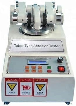
So I ramped to 40 amps in 2 minutes and held it there for 40 minutes. After the time was up I took out the panels and measured 2 mils with the permascope....SUCCESS! I even doubled my Taber abrasion test from 20 mg loss to 10 mg loss.
. . . THEN I tried the same thing with 6061 panels using the same 720 calculations and the same Sq Ft, but only reached 1.5 mils. So I put it back in the tank for another 12 minutes and finally got 2 mils.
So why did this happen? Am I missing something from the calculations? Does the 720 rule not apply to all alloys?
My understanding was that if I followed the 720 rule I would be able to consistently get the desired mils in the calculated time....every time.
Chris
Anodizing Shop Employee - California
July 30, 2010
|
A. 7075 will have a lower finishing voltage @ 2 mils than 6061 will at the same current density. What is the maximum voltage your rectifier puts out? If it's less than 60-75 volts, you may see a drop off in amperage when anodizing 6061 (depending on the heat lot), and if that's the case, the 720 rule won't apply as accurately. Did you notice a drop off in your current readings as you approached the end of your cycle time when anodizing the 6061?  Marc Green anodizer - Boise, Idaho A. Chris - Colorado Springs, Colorado A. The relatively approximate 720 rule varies with dissolution rate and that varies with all the parameters, yes even alloy, and concentration of free acid, and dissolved aluminum, impurities, agitation, accuracy of ammeter, how much current went on the rack, etc.  Robert H Probert Robert H Probert Technical Services Garner, North Carolina  |
Q. Hi, everyone. I would like to know if anyone can tell me how long the process for 2011, 6061, 5052, 2024, 7075 Aluminum is from etch to finish, and any other Aluminum materials from Start to Finish. My line seems to put out some good but certain material is not great at all. I have a great dye and would just like to know what we might be doing wrong.
Sarah SmallwoodGeneral Manager - Garland,Texas USA
October 6, 2011
Mixing different size parts for anodizing
for Shops, Specifiers & Engineers
avail from eBay, AbeBooks, or Amazon

avail from eBay, AbeBooks, or Amazon
avail from eBay, AbeBooks, or Amazon

avail from eBay, AbeBooks, or Amazon
avail from eBay or Amazon
(as an Amazon Associate & eBay Partner, we earn from qualifying purchases)
Q. Hi friends,
I have different sizes of aluminium parts ranging from 0.0020 to 0.230 m2. If I load all the parts in one fixture to anodize them at a time, is there any adverse effect on parts, while I am supplying the amps with respect to each part area?
- Abu Dhabi, UAE
November 18, 2013
A. Hi Aijazullah. I don't think you will have trouble from mixing these various size parts into the same load.
However, we appended your inquiry to this existing thread as food for thought: because if you mix different parts, you may risk mixing different alloys ... and that is likely to give you problems. Good luck.
Regards,

Ted Mooney, P.E.
Striving to live Aloha
finishing.com - Pine Beach, New Jersey
Ted is available for quick help
or longer-term assistance.
A. Theoretically no problem as Ted says, however, I do not understand your size. If that 0.002 (inches or millimeters?) is a "thickness" of a wide panel then you best keep separate, make contact in several places, and ramp up unusually slow giving time for the outside edges to insulate while the current slowly moves inside, other wise you will burn holes at the contact area. Also be aware that on metal this "knife-edge-thin" the oxide may crack on the edges.

Robert H Probert
Robert H Probert Technical Services
Garner, North Carolina

A. Hi Robert. I think Aijazullah is saying that his parts range from .002 square meters [3.1 square inches] in surface area to .23 square meters [356 square inches], without offering any info on their length, width, depth, or shape. Your warning that thin parts can present their own special problems is good! Thanks.
Regards,

Ted Mooney, P.E.
Striving to live Aloha
finishing.com - Pine Beach, New Jersey
Ted is available for quick help
or longer-term assistance.
Q. Dear friend.
Am dealing with hard anodizing for 7075 material, with a specific set of inputs like 250 A/m2, temperature 0 to -5 °C, concentration of sulfuric acid -20% by weight.
Am getting different thickness for each run, so what could be the reason for this? Moreover, I supplied the current in 4 steps; like if 20A is required then I provide like 5 amps for 5 min, then increase another 5 amps for next 5 min, finally when it reaches 20A leave it for remaining time. This is the method I am using for total amps calculated for the parts whether it is 20A, 40A or 100 A.
Any suggestions or feedback will be help for me.
- Abu Dhabi, UAE
April 1, 2014
A. 1. If part to part, then on the rack you are not getting the same current on each part, so,file the contacts more blunt with a wider contact area.
2. If load to load, then the problem is where the rack hangs on the load bar, clean it (hopefully it is not aluminum) between each load by abrading with an abrasive matt like "Scotchbrite". If the load bar is aluminum, you must scrub it with abrasive between each load (Hey, aluminum oxidizes rapidly and you have to scrub off the oxidation).

Robert H Probert
Robert H Probert Technical Services
Garner, North Carolina

|
A. Aijazullah, no disrespect intended here...but you've been asking a multitude of very basic questions that every anodizer should know. Have you considered attending a 101 workshop put on by the AAC, or thought about purchasing a book or two? Or perhaps check this site for available consultants?  Marc Green anodizer - Boise, Idaho Hi Marc, - Abu Dhabi, UAE
People like Marc know that their knowledge came from years of formal training and/or hands-on learning, and could never, ever have been acquired simply by asking questions in an internet forum. So they try to make that helpful point and suggest a course or a book or a visit from a consultant for the properly sequenced "tutorial" style that is so essential to efficient learning. Take it from me, I've posted every single Q&A on this site for 25 years now, yet after dealing with a quarter million of them I remain woefully ignorant on the many metal finishing topics where I lack actual hands-on experience :-) Regards,  Ted Mooney, P.E. Striving to live Aloha finishing.com - Pine Beach, New Jersey Ted is available for quick help or longer-term assistance. |
![]() Well said Ted. To add to that, I'm not sure that some folks realize how difficult it can be to answer somewhat vague questions on an internet forum, especially when it comes to metal finishing, and the large amount of variables that are in play. I would wager that I could go observe Aijazullah's operation and solve most of his issues pretty easily, however, the challenge of doing it online, without all of the info necessary can be a daunting one.
Well said Ted. To add to that, I'm not sure that some folks realize how difficult it can be to answer somewhat vague questions on an internet forum, especially when it comes to metal finishing, and the large amount of variables that are in play. I would wager that I could go observe Aijazullah's operation and solve most of his issues pretty easily, however, the challenge of doing it online, without all of the info necessary can be a daunting one.
This was the main reason I suggested a consultant, Aijazullah...not to dissuade you from asking questions. Sure, a consultant, or formal education may cost a bit upfront, but it will save you money and headaches in the long run.
A. Anyhow, to toss out some potential things for Aijazullah to consider in relation to his question:
1. Sounds like you have a manual ramp? I suggest a programmable one. It eliminates human error, or forgetting to ramp to the next step. Also, your ramp sequence/time seems a bit unnecessarily slow to me, and will add to your cycle times. At the current density you mentioned, you should be looking at approx 1 hour of cycle time for a typical 2 mil hardcoat.
2. As Robert asked, you weren't real clear on whether this thickness issue occurs in the same run, or from run-to-run.
3. Are you confident in your surface area calculations?
4. Are you using the same racking material and techniques in all of your runs?
5. Is the voltage output of your rectifier large enough for hardcoat anodizing (at least 75 volts)?
6. How much variance are you seeing in your coating thickness?
7. Do you calibrate your eddy current meter often? Are your measurements being taken far enough away from any edges or corners of your parts?
8. These would be things I'd look at if you're seeing a run-to-run difference. If you're seeing part-to-part difference in the same run, that opens up another realm of possibilities, starting with the material itself being from the same heat lot, to the racking and anode bar cleaning suggestions that Robert mentioned, to the actual conditions in your anodizing tank (evenly placed cathodes, adequate agitation, good bath temperature control, etc, etc).
I'm done here :)

Marc Green
anodizer - Boise, Idaho
![]() Thanks a lot friends; I appreciate your assistance.
Thanks a lot friends; I appreciate your assistance.
- Abu Dhabi, UAE
April 9, 2014
time = mic x (1/0.33) x (1/current density)
where
time: in minutes
mic: anodic film thickness in microns
current density: current in Amps divided by the load in sq. dm. This is generally 1.2-1.5 A/sq. dm."
Q. Does this formula hold good for 270 g/l H2SO4 at 25 °C ?
Also, can anyone tell me what is the optimal reading in a hydrometer in Type 2 sulfuric acid anodising process?
- Hyderabad, TG, and India
July 26, 2015
A. Hi Durga. The "720 Rule" in anodizing and its metric equivalent, and analogous deposition rates for electroplating, are all based on Faraday's Law of Electrolysis, which is that 96,485 coulombs (ampere-seconds) equates to one gram equivalent weight of deposition.
This is not an empirical rule, but is based on first principles, and conversions of atomic weight & Avogadro's constant -- i.e., if you pump the electrons from anode to cathode, the atoms/ions will follow. Thus, solution concentrations and temperatures have nothing to do with it in theory. In practice, of course, the reaction is not 100% efficient, and the efficiency may depend upon temperature and concentration, and ongoing dissolution of the anodizing in the acid may also.
Wernick, Pinner, & Sheasby has a subchapter about "The Coating Ratio" which shows some adjustments for different alloys and coating weights -- but sorry, I don't know if anyone has ever published "adjustments" of the sort you envision for different anodizing concentrations and temperatures. But looking at the graph in Wernick, Pinner, & Sheasby, I suspect the alloy composition and tempering has a much more disruptive effect on the theoretical calculation than the concentration and temperature :-)
Regards,

Ted Mooney, P.E. RET
Striving to live Aloha
finishing.com - Pine Beach, New Jersey
Ted is available for quick help
or longer-term assistance.
A. A hydrometer is a very poor way to control acid concentration other that the initial make up. The reason is the tank will gradually build up aluminum, copper and other metals from the alloy being anodized and they increase the density of the solution. It is also temperature dependent.
A simple acid / base titration is far superior.
- Navarre, Florida
Q. Tank size is 3 ft X 3 ft X 3 ft and rectifier rated current 750 amperes, 24 VDC and I hold the lot dipped in tank for 60 minutes and get the coating thickness 1 mil (24 microns). How many components of 10 Square feet surface area, can I dip at same time without changing the other related parameters?
Manjeet Singh- Chandigarh, Haryana, India
August 30, 2016
A. The 720 rule implies that the thickness build is a straight line. No it is not, it is negative exponential, with time the rate of thickness falls off to eventually becoming a level line - no further thickness. Be very careful what range to try to use the 720. Do not dare use it on heavy thick hardcoat.

Robert H Probert
Robert H Probert Technical Services
Garner, North Carolina

![]() Thanks Bob. I had to think about that for a bit because I know that electrochemistry doesn't violate Faraday's Law, but I also knew your advise was completely sound and correct :-)
Thanks Bob. I had to think about that for a bit because I know that electrochemistry doesn't violate Faraday's Law, but I also knew your advise was completely sound and correct :-)
The explanation of course is that other things are going on --
First, the 'efficiency' can start to decrease, with the electrical power releasing hydrogen and oxygen instead of building thickness;
Second, the sulfuric acid is attacking and dissolving the anodizing, and as the coating gets thicker and the build-up grows slower, the dissolution by sulfuric acid is probably not slowing down.
Regards,

Ted Mooney, P.E. RET
Striving to live Aloha
finishing.com - Pine Beach, New Jersey
Ted is available for quick help
or longer-term assistance.
Q. I have a lot size of 135 sq ft and the cathode size is 45 sq ft, with 2500 Amp rectifier, 24 V. Please suggest the time it will take to give 15 micron anodizing coating.
Nitin Kumar- Greater Noida, India
December 31, 2018
A. Hi cousin Nitin. You can't anodize at arbitrary voltages, arbitrary current density, and arbitrary times. So first, choose your current density. Anodizing expert Robert Probert suggests 12 ASF for general job shop work. Apply the 720 rule and you learn that it will take 720/12 or 60 minutes to produce one mil of oxide, which is 25.4 microns. So your anodizing time will be 60 x 15/25.4, or 35 minutes per load.
You haven't specified your tank size and volume but if your cathode size is 45 sq. ft., you probably have room to anodize a load size of something like 45 sq. ft. (but study Ward's reply about the various possible limitations); you obviously have more than enough rectifier capacity. Good luck.
Regards,

Ted Mooney, P.E. RET
Striving to live Aloha
finishing.com - Pine Beach, New Jersey
Ted is available for quick help
or longer-term assistance.
Q. Good Morning, my name is Michael and I need a bit of help. We are in the process to anodise.
I need to anodise parts to 0.25 microns. the Voltage of the rectifier is 12V and the AMPS the parts are running on is 140A
We have used a 1000L flowbin as an anodising tank and there is about 800L in it. Ratio mix 15% sulfuric acid and 85% Water
How long will it take to reach 0.25 microns with the above supplied specs
Thanking you in advance
Michael
- Cape Town,Western Cape, South Africa
March 28, 2019
A. Hi cousin Michael. There is a missing piece of data that is required for this calculation, namely the surface area of the load you are anodizing. The "140 Amps" you are trying to use in your calculations is not useful until you can divide it by the surface area and tell us the current density (Amps / sq. dm or Amps / sq foot). Good luck.
Regards,

Ted Mooney, P.E. RET
Striving to live Aloha
finishing.com - Pine Beach, New Jersey
Ted is available for quick help
or longer-term assistance.
A. 0.25 microns is extremely thin, are you sure it's not 25 microns? If you're running by constant voltage and not current (the reason people are asking about surface area), I would estimate around an hour and 30 minutes or more to get a 25 micron coating. 12V is a little low for constant voltage anodizing.
Constant current is a better way to go, as your results will be more predictable. Do a search for "720 rule" on this site for more info regarding constant current anodizing times.
If you're indeed only trying to get 0.25 microns, maybe 3-5 minutes, depending on your ramp time. That's just a rough estimate at best.

Marc Green
anodizer - Boise, Idaho
A. Based on what you have for equipment I think you are beating a dead horse. Most type II anodizing is done with DC power supplies rated at 18-24 volts. When using 12 volts I doubt that you can get 25 microns which is a standard for type II. 15 microns would be acceptable. Save up your pennies and purchase a rectifier which can do what you need to be done. Set it at 16-18 volts with 500 amps available and watch your work improve.

Drew Nosti, CEF
Anodize USA
Ladson, South Carolina

Same anodizing voltage, time, & area as always ... but thickness is lower
Q. I have a sulfuric anodize Type 2 Class 1, 21 Volts/10 min.
For years I got a thickness of 0.38 mils, but recently the panels started to get burned and with low thickness (0.15-0.20 mils). I changed the lead cathodes and the burning problem was solved; after I changed the copper bar the thickness improved to 0.31 mils,
But I want to know why I cannot reach the 0.38 mils again, could you give me advice please?, I'm using the same area because it is in panels (coupons), and the rectifier was checked.
Diana Balderas- Mexico
April 16, 2020
A. Higher temp = slower thickness. Higher free acid = slower thickness. Both cases affected by dissolved aluminum.
Assuming racking and agitation has not changed, we need to know the free acid, aluminum, temp and current density to answer your lower thickness question.

Robert H Probert
Robert H Probert Technical Services
Garner, North Carolina

|
A. THIS IS A RECORDING! (... sorry I had to).  Drew Nosti, CEF Anodize USA Ladson, South Carolina  Q. I have 12 amp/ft2, the spec range is between 12 and 16amp/ft2.
If I increase the current density I will have more thickness, but the area (resistance) has been the same since many years ago and the voltage too. I don't have data of current density for the last years before this situation.
I have cleaned the installation to avoid false contacts. Diana Balderas [returning]- Quer´taro, Mexico |
A. The rack hangers look like aluminum, if so, the contact resistance comes into question; so if the anode load bar is also aluminum, there is no question that with the agitation the curved hook to the load bar makes an intermittent contact. So Scotch brite the rod and under the hook on each load.

Robert H Probert
Robert H Probert Technical Services
Garner, North Carolina

A. 1. make sure your rectifier got calibrated;
2. At current density of 12 A/ft^2, it should not burn your panels. It most probably that some of your panels loose contact during anodizing (with less thickness) while others got burnt.
-Singapore
A. Here I go again?? Just for giggles take one part or panel and before it is processed wipe it down with acetone ⇦ on eBay or Amazon [affil link] Flammable! . Then run it through with the other parts and see if there is any difference in the thickness recorded. I am thinking that something in pretreatment changed? Also do you use a deox before anodize?

Drew Nosti, CEF
Anodize USA
Ladson, South Carolina

A. Diana
If you still have panels from when you were getting the thicker coating, consider measuring side-by-side with your recent panels to ensure that the issue is not measurement related.
Also, if using a 3-phase rectifier, ensure that all 3 phases are proper. I have seen related issues in hard anodize where 1 leg / phase of the power was out. The service provider corrected the issue (transformer) and the problem went away.
- Green Mountain Falls, Colorado
Q. Thanks for all the answers, the rectifier was having troubles and now it has been solved; now I have a thickness of 0.35 mils that's perfect for sulfuric anodize Type 2 class 1!
Now I am working in sulfuric anodize Type 2B, we use the same bath, these are the conditions:
Sulfuric acid concentration = 11.88% Vol, spec range 11-13% Vol.
Aluminum = 3.78 g/L, the spec limit is 15 g/L.
Temperature: 68-72 °F. Commonly it is °F.
Voltage = 17V
Time = 5 minutes
Thickness requirement= 0.1-0.2 mils. For now I hardly get to 0.1 mils.
I found that we are not achieving the current density required by spec that is 12-16 amp/ft2 in Type 2B.
In the first effort I used:
Voltage = 17V
Time = 5 minutes
Area = 18.32ft2
Current average I got was = 189.5 amp
Current density = 10.33 amp/ft2
After that I decided to reduce the area, to increase the current density, according to the formula: density = current/area.
Here are the results:
Area = 13.32 ft2
Current average I got = 122.5 amp
Current density = 9.19amp/ft2
I cannot achieve the value recommended by the spec, do you know another way to increase the current average? I have calculated that at least I need 220 amp to 290 amp in current average to get the current density required.
Thanks
- Mexico
A. Diana
If the spec is limiting you to 17 volts maximum, I would check to ensure my bussing is not introducing resistance, and racks are capable of carrying the required current. Maybe look at the cathodes & cathode:anode ratio as well.
- Green Mountain Falls, Colorado
A. With 17V, setting your acid concentration and bath temperature at upper limit will help to increase the current density (if surface area is maintained the same) but I am still in doubt that you would get CD higher than 12 A/ft^2. you can try to reduce the surface area to 4 ft^2 while other parameters unchanged.
John hu
- Singapore
⇦ Tip: Readers want to learn from your situation;
so some readers skip abstract questions.
Q. Which is the best way to solve the micron issue?
My question is that what is the perfect timing for provided micron per minute and what will be the sulfuric qnty in anodising tank using 18 volts.
Rajesh Jangra- Bahadurgarh Haryana ( India)
March 22, 2021
A. Hi Rajesh. Unfortunately I think we're having language difficulties -- I'm not understanding your question.
So we appended your question to a thread which talks about ramp time and anodizing time vs. thickness. As for sulfuric acid, common round-number values for sulfuric acid concentration for anodizing are 10% by volume or 15% by weight, which end up not being that far apart.
Luck & Regards,

Ted Mooney, P.E. RET
Striving to live Aloha
finishing.com - Pine Beach, New Jersey
Ted is available for quick help
or longer-term assistance.
A. The 720 rule is based on a one mil thickness which can be converted to 25 microns. Therefore 24 ASF should give you 1 mil or 25 microns in 30 min. 30 ASF should give you 1 mil or 25 microns in 24 min. Please remember these numbers are close but not dead on, so be understanding of some differences based on the alloy. It still beats the results of voltage anodizing.

Drew Nosti, CEF
Anodize USA
Ladson, South Carolina

Q. Hello, please I will like to know the calculations involves in determining the quantity of aluminium profiles (load) on a carrier bar in order to be anodized in the anodizing bath, considering the electrolytes (H2SO4), the Amperes, voltage, and the resulting film thickness (micron) to be generated on the anodizing profile after anodizing.
Thanks in anticipation for your response
- Lagos, Nigeria
May 23, 2021
A. Hi Abdulazeez_Shewu. First you must determine the surface area of the profiles. Then you can calculate the required amperage based on the fact that anodizing works best at a current density of, say, 12 ASF for general jobshop work. Now that you know the surface area and the current, you can apply the 720 rule to relate anodizing thickness to anodizing time. Voltage will vary to suit the current you are applying and the alloy, but will probably not be less than 12 volts or more than 16.
Luck & Regards,

Ted Mooney, P.E. RET
Striving to live Aloha
finishing.com - Pine Beach, New Jersey
Ted is available for quick help
or longer-term assistance.
A. Exactly what Mr Mooney posted, but note that the "720 rule" is only approximate, it is negative exponential but in the regular Type II range it is close enough AND that if you process the 2000 alloys, because of lower conductivity, you will need to have 21 volts to get 12 amps per square foot (at 180 g/L free acid).

Robert H Probert
Robert H Probert Technical Services
Garner, North Carolina

Q. Hi,
Simple question that I wasn't able to find any answer yet.
I am wondering if when mixing two (2) different part size (surface) in the same bath affect the anodizing build-up on the smaller surface parts?
Part #1 = 1 sq.in.
Part #2 = 2.5 sq.in.
Thanks
- Quebec, Canada
September 3, 2021
A. Hi Leo. This should not by itself be a problem. However, the two parts must be the same alloy or all bets are off :-)
Luck & Regards,

Ted Mooney, P.E. RET
Striving to live Aloha
finishing.com - Pine Beach, New Jersey
Ted is available for quick help
or longer-term assistance.
Q. Hi Ted,
Thanks for confirming that they would anodize equally on their entire surface. I assume we need to see this as an electrical circuit equivalent. Do you or anyone on this forum happen to have any reference to this so I could read more about it?
Yes, I had presumed that one cannot mix alloys.
Regards,
Leo
- Quebec, Canada
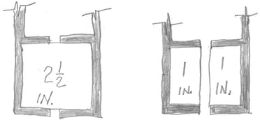
A. Hi again. I can't offhand think of a reference which explains the point; but as a thought experiment, picture a 2-1/2 square inch part mounted on an anodizing rack with excellent contact all around; now picture taking a hacksaw and cutting a slot through it -- it really doesn't change much.
Luck & Regards,

Ted Mooney, P.E. RET
Striving to live Aloha
finishing.com - Pine Beach, New Jersey
Ted is available for quick help
or longer-term assistance.
![]() Good day Ted,
Good day Ted,
Thanks for your reply and supporting drawing. I was able to find my answer in Posting 30512 from Paul_Yursis. Following Ohm's law, the internal resistance is within the electrolysis, not the aluminum part that I tend to believe.
Thanks again for shedding some light,
Leo
- Quebec, Canada
Q, A, or Comment on THIS thread -or- Start a NEW Thread

