
| Search our quarter-million Q&As |
Home of the finishing HOTLINE since 1989
-----Possible to get uniform thickness over the component in zinc plating?
Q. As I'm a fresher in this plating line, we had an issue regarding the uniform plating thickness of around 13 micron all over the component. Where the component is not a plain sheet, the dimension of the component 300 mm length * 50 mm width & 3mm thickness. The component is "s" shape. We are doing alkaline zinc plating the variation in the regular plating is 1:2 where the component is fixed vertically; we find low thickness at the top and high thickness at the bottom;
Pls give suitable remedy for the above issue.
Regards
PLATING SHOP EMPLOYEE - CHENNAI, India
October 21, 2010
A. Hi,
In the electroplating process its very difficult to get an uniform thickness, try Hot dip galvanising or zincating by dip spin method.

Praveen Kumar
plating process supplier
Mumbai, India
November 4, 2010
A. Hi,
In order to obtain uniform layer thickness in electroplating, you must use conforming anodes and/or current thieves.
- Geldrop, Netherlands
November 4, 2010
A. Or shields or a combination of all of the above.
I would first see if increased agitation and placement of the anodes would be enough.
- Navarre, Florida
November 5, 2010
A. Dear Mr Bala,
The component you describe is not too difficult: just a wild hunch - the plating tank is too small to accommodate this part leading to the problem you are facing. The further you are able to position this part away from the anodes the better will be your plating thickness distribution.
I have plated larger parts with complex shapes with almost uniform plating - an alkaline process helps.

Khozem Vahaanwala
Saify Ind
Bengaluru, Karnataka, India

November 24, 2010
Rack Distribution Study: Too much zinc plating thickness variation
Q. Hello,
We are zinc plating a Steel stamped disc. There seems to be too much plating thickness variation among parts at different locations in the rack. Parts on the top (near to the bus bar) have highest thickness and bottom parts have the least thickness - as expected due to current density will be higher at the top and decreases as we go down.
Also, on the steel stamped disc, the side closest/facing to the anode has higher plating thickness. I understand, all these are common in plating processes and cannot be avoided.
When we did a rack distribution study, my range in the plating thickness goes up to 20 microns? How do I reduce this variation ? Any suggestions ?
Thanks
- Pell City, Alabama,USA
May 8, 2020
A. Hi Arunkumar. Cyanide or alkaline non-cyanide zinc plating gives better thickness distribution than acid zinc, so if you are currently doing acid zinc, that's one path forward although it's a big step.
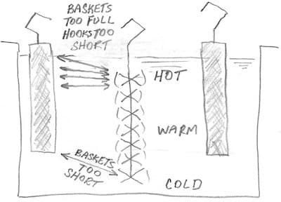
I don't think I accept your 'given' that "current density will be higher at the top and decreases as we go down." If you have good agitation so there is no temperature stratification, I don't see why that would be so.
It may be that your anode baskets ⇦ huh? are too short, making for a long current path to the parts at the bottom of your racks. The very easiest thing to try is to not fill the anode baskets all the way up, to increase the distance from anodes to top-most parts. If that helps, you might consider fitting your anode baskets with longer hooks, so they start lower and end lower.
Regards,

Ted Mooney, P.E. RET
Striving to live Aloha
finishing.com - Pine Beach, New Jersey
Need quick confidential answers? $25
Need project assistance? $100/hr.
Q. Ted,
Thanks for the reply. I will focus on improving agitation, see it is quick fix.
Is there any literature/guidelines on what optimum position of the part from the anode or optimum hook lengths is to get the best thickness distribution.
Thanks.
- Pell City, Alabama,USA
May 12, 2020
A. Hi again Arunkumar,
The principal is simply that the thickness will be in proportion to the current density by Faraday's Law, and that the current density will be most uniform when the parts are the same distance from the anodes and the anodes start and end a couple of inches short of the top and bottom parts.
There is "electrochemical modeling software" that will attempt to help you with such design work but I've never used it.
Regards,
Ted Mooney, P.E. RET
Striving to live Aloha
finishing.com - Pine Beach, New Jersey
Need quick confidential answers? $25
Need project assistance? $100/hr.
May 2020
Q. Hello,
Can we do a rack distribution study with multimeter to understand High current and low current area ...then suitably place current thieves/shields to make optimum rack (uniform current distribution) - Do rack manufacturers do this study ??
- Pell City, Alabama, USA
May 14, 2020
A. Hi again. It is possible to measure the current density at different positions on a plating rack but not, as far as I know, with a simple multimeter. It requires a special current density probe as discussed in topic 44947.
As previously mentioned it is also possible to estimate the current density at different spots with the purchase of 'electrochemical modeling software'; but do your own googling because we can't offer brand or sourcing suggestions (why?) I haven't heard of rack manufacturers doing such studies but I suppose they could.
You haven't told us yet whether you are doing acid vs. alkaline plating, and whether you are a captive or a job shop, but I've never heard either of thieves being used in zinc electroplating nor even of job shops employing shields for zinc plating; as I said previously they are usually restricted to more exotic applications. If you are getting too much thickness at the top of the racks I think the first two steps should be improving the agitation to reduce temperature stratification if necessary, and not filling the anode baskets so much that the topmost parts have more anode area proximate to them than the other parts have. I suppose it's also possible that the splines on your plating racks are not rated for the current you are now applying. Peace.
Regards,
Ted Mooney, P.E. RET
Striving to live Aloha
finishing.com - Pine Beach, New Jersey
Need quick confidential answers? $25
Need project assistance? $100/hr.
May 2020
Sorry! Finishing.com is temporarily Read-Only.
Please maintain your bookmarks! Although Ted Mooney is retiring, finishing.com is not!
It will have a new owner/curator very shortly!