
| Search our quarter-million Q&As |
Home of the finishing HOTLINE since 1989
-----Achieve uniform thickness in electroplating
< Prev. page (You're on the last page of this topic)
Q. Hello people.
I'm facing an issue while electroplating Ag on Cu.
Not able to get constant thickness on job.
For ex: job pieces at center of the jig are OK with the thickness whereas, the pieces placed on the start and end of the jig have more thickness in spite of correct contents and current as per area.
Kindly help me with the solution/ answer for the same.
Thank you.
Plating Shop Employee - Nasik, Maharashtra, India
November 19, 2015
A. Hi Nikhil. We appended your inquiry to a thread which talks about the many different approaches to resolving this problem. But the easiest and most obvious way to improve your situation sounds like removing the anodes at the ends of the tank.
Regards,

Ted Mooney, P.E. RET
Striving to live Aloha
finishing.com - Pine Beach, New Jersey
Need quick confidential answers? $25
Need project assistance? $100/hr.
November 2015
Q. Dear Sir,
I Have Plate Duplex Nickel Hard Chrome on outer surface of Cylindrical Tube, why not occur Surface Thickness same/uniform on tube? (i.e., Chrome Thickness vary at Top, Middle & bottom side of tube)
Employee - Aurangabad, Maharastra, India
January 17, 2016
A. Hi Rajkamal. Per Faraday's Law, the thickness at any spot is directly proportional to the current flow to that part (this is a slight exaggeration as there are some more obscure relationships between thickness and other partameters, but it's almost surely the problem here). To get even plating thickness to different spots you'll need to insure even current flow to the different spots. One fairly common problem is anode rods being too long, so you get a lot of current flow to the bottom of the part. Good luck and feel free to send sketches.
Regards,
Ted Mooney, P.E. RET
Striving to live Aloha
finishing.com - Pine Beach, New Jersey
Need quick confidential answers? $25
Need project assistance? $100/hr.
January 2016
Q. I Want to Reduce the Nickel Percentage from Present of around 5 - 6 Microns to 1 - 2 microns. Please I Need help.
Pintu Shah- Jamnagar, Gujarat, India
September 25, 2016
A. Hi Pintu. Your posting is a bit too short to be understood. Are you saying that your present nickel plating thickness is 5-6 microns and you want to reduce the thickness to about 1-2 microns, or are you saying that the thickness varies over the part by 5-6 microns and you would like to reduce the variation to 1-2 microns?
Reducing the thickness to 1-2 microns would be very easy; simply cut the plating time or the plating current proportionally. But there are very few applications where 1-2 microns of nickel plating would be satisfactory. Perhaps for certain diffusion coatings or strikes, I suppose, but not as an actual plating layer. 5 microns is required for even "mild" environmental conditions (indoor applications). What are the parts? What is the application?
Reducing the variation in plating thickness is difficult. We would need a lot of info about the substrate material and geometry, and the target plating thickness. Good luck!
Regards,
Ted Mooney, P.E. RET
Striving to live Aloha
finishing.com - Pine Beach, New Jersey
Need quick confidential answers? $25
Need project assistance? $100/hr.
September 2016
Q. Hi all,
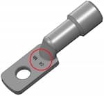
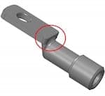
I realize electrolytic nickel on aluminum terminals. After measuring the thickness of nickel, in some areas, we lose up to 50% of thickness (area marked in red).
Terminals are screwed on a rack that holds about forty terminals. The cathode is placed parallel to the tongue of the terminal, at mid-height of the rack and all the terminals.
I have read some posts and I think geometry favors higher or lower current density. Maybe the distance terminal/cathode can also be incriminated.
So, this is my question: how I can greatly reduce this variation in thickness?
Regards,
- Pompadour, Limousin, FRANCE
October 26, 2016
A. Hello Jeremy,
I would first check the calibration on your rectifier. Next, contact points between anode and cathode buss bars, and last for any polarization in your anode material supply. Although it is not uncommon to have a fluctuation in thickness from high to low current density areas, or an area where metal must travel further than the shortest path to the work, 50% less seems a bit high for the part in your image. If once you have insured all currents and anodes are preforming correctly you are still left with an an unacceptable difference in thickness, it's time to consider auxiliary anodes. An auxiliary anode is a supplementary anode that alters the current distribution in electroplating to give a more uniform plating thickness. A small piece of anode material placed in close to the area you are having trouble with connected to the anode current supply.
If it is still not as uniform as you would like you could move over to electroless Ni. Electroless Ni solutions are touted for their uniformity in thickness compared to any electroplating solution. Good luck.

Chance Dunstan
Electroplating/Forming/Coating Manager
Placerville, California USA
November 4, 2016
A. Hello Jeremy, Chance had some good suggestions and I just wanted to add a few more. I experienced a similar problem a few years ago and was given the task to reduce thickness variation in our Ni plating tank. First I had to bring the anode to cathode ratio down to 2:1. We were at about 5:1. Then I lowered the current density to 20 ASF, we were at 28. Higher current densities will favor the high CD areas on the part. Lower CD's will help you deposit more metal in the LCD areas. You will have to increase dwell time accordingly to meet your thickness specs. Hope this helps.
Mark BakerProcess Engineering - Phoenix, Arizona USA
November 16, 2016
Ideal Anode to cathode distance in Nickel plating
Q. I am doing Nickel plating on thin perforated metal. It is modified watts bath with temperature around 65 °C. pH 4.0
My problem is Nickel plating in some small holes which is not desired. Is anode cathode distance playing a role? Of course higher distance will result in loss of electricity (high voltage) is there any standard desired distance? Too close anodes of course creates roughness. Any maximum voltage? Current density desired as high as possible.
consultant - Adalaj, India
July 22, 2017
A. Hi Kaushik. Sorry but I do not understand the main question regarding you getting unwanted plating in holes. Unwanted plating is usually stopped by masking; but since I am misunderstanding you, a picture with labels showing the problem would probably help.
My career was mainly as a plating equipment engineer, designing, starting up, and troubleshooting plating lines. So I know very little about the deeper academic end of electrochemistry, but feel that most questions of anode-to-cathode spacing revolve around the simple practicalities: You don't want the anode and cathode to ever accidentally touch, and you don't want them so close that the plating on the close spots burns; but you want them reasonably close because solution resistance is terribly costly. Greater spacing requires higher voltage rectifiers, consumes more electrical power, requires more cooling, needs bigger tanks with greater capital cost, requires more fume ventilation and more make-up air, etc. This is, to me, the 'desired standard distance'. Again, for a deeper understanding you'll need an answer from someone with different background & experience.
But I do not agree that close spacing "creates roughness". Roughness, as most people use the term, implies the deposition of particulates ... whereas if the anodes are well bagged and you have efficient filtration, roughness should not be a problem. Too much current causes burning, which is rough, and this may be what you are referring to. I think you might look into the 'shields' discussed on this page as a way to minimize that burning, and to discourage plating in the areas where you don't want it. Best of luck.
Regards,
Ted Mooney, P.E. RET
Striving to live Aloha
finishing.com - Pine Beach, New Jersey
Need quick confidential answers? $25
Need project assistance? $100/hr.
July 2017
A. Hi,
Send us a photo of the part.
To have good leveling a longer distance between anode and cathode is important; if it too close the current will go a shorter way. If there are holes in the part you should use inductive/auxiliary anodes.
Regards

Anders Sundman
4th Generation Surface Engineering
Consultant - Arvika,
Sweden
July 27, 2017
Q. How to minimize plating thickness generation by plating process?
Basant kumarSecure Meters ltd. Udaipur (Raj)India - UDAIPUR, Rajesthan, India
August 23, 2018
A. Hi Basant
Please do us a favor and re-post your actual situation? Who you are, what you do, why this is important to you, what type of plating you do, what unevenness you experience, etc.
Changing from acid to alkaline might help, brighteners and levelers might help, shields might help, thieves might help, racking differently might help, rotation might help, every plating variable from temperature to pH to concentration to current density has some effect on distribution. Thanks for your understanding. Regards,
Ted Mooney, P.E. RET
Striving to live Aloha
finishing.com - Pine Beach, New Jersey
Need quick confidential answers? $25
Need project assistance? $100/hr.
August 2018
Q.
Hi Ted Mooney, thanks lots for fast response to us.We are interested to know how to minimize electro tin, nickel, silver, copper plating thickness variation in barrel plating process. We have more than 1000 suppliers with plating setup. We are world class electronics energy meter manufacturer, and using metal components in our products like screws, nut, bolts, plates, etc.
Thanks & Regards,
Basant kumar [returning]Secure Meters ltd. Udaipur (Raj)India - UDAIPUR, Rajesthan, India
August 24, 2018
A. Hi again, Basant. We appended your inquiry to a thread on the subject which you might wish to study. Shields & thieves would not be applicable to barrel plating, but everything else I mentioned would be.
I would suggest that you start tabulating which plating shops are doing a satisfactory job in controlling thickness and steer your work towards them. The idea that hundreds of plating shops don't understand the importance of uniform thickness and the ways to achieve it, but someone will be able to tell you in an internet posting what to tell them to fix it, just isn't realistic. Send your work to the better platers. Good luck.
Regards,
Ted Mooney, P.E. RET
Striving to live Aloha
finishing.com - Pine Beach, New Jersey
Need quick confidential answers? $25
Need project assistance? $100/hr.
August 2018
Uniform Flow of Current Density in the Plating Tank
November 28, 2018Q. Dear All,
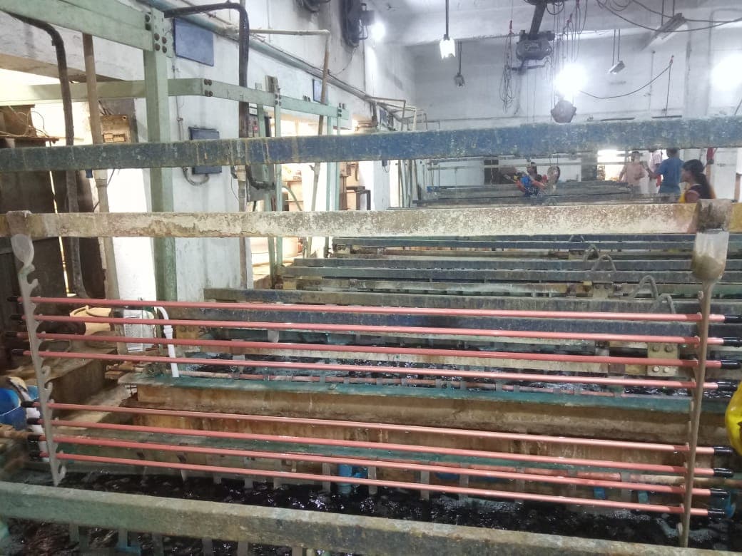
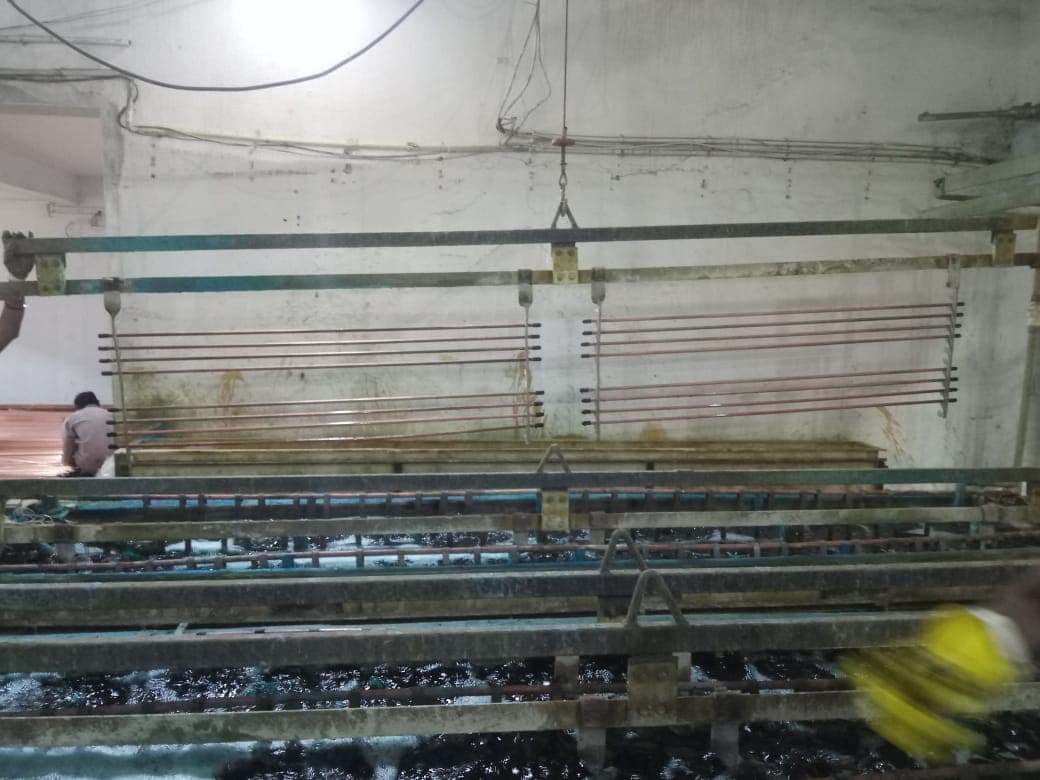
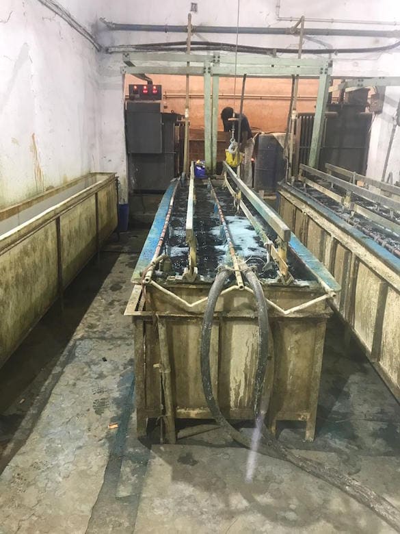
We are currently electrodepositing copper on mild steel. The pictures I shared to the email will help understand the current positioning of our cathodes, shape and size of Jigs to hold the cathodic material and the electrical connection made to the rectifier.
We are facing the below two major problems :
A. The copper deposition seems to be varying on the cathode depending on its position on the Jigs. The upper two and the lower two has a higher deposition rate than the middle four articles.
B. The copper deposition seems to be varying on the cathode depending on the placement of Jigs on the rack. The Jigs placed at a position closer to where the electrical connection are made receives a faster copper deposition than the jigs placed farther away.
C. There is a dark grey colour sludge that is obtained in the bottom of the tank when the tank undergoes cleaning, we are speculating this sludge to be the reason for the roughness obtained on the cathode surface. Our speculation is made based on the thought process that as the sludge accumulates on the bottom where there is air agitation
⇦ huh?
, which in turns agitates the sludge and thus causing the roughness.
Positioning of Rods on Jigs
Rack with Jigs
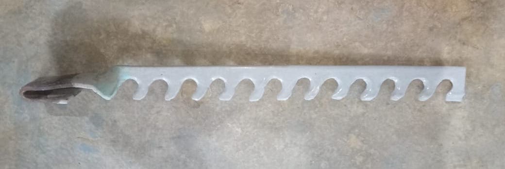
Jigs - Before Coating
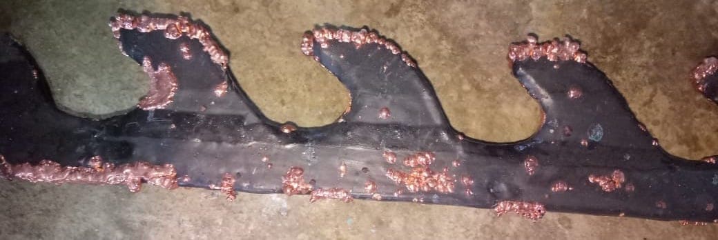
Jigs - After Coating
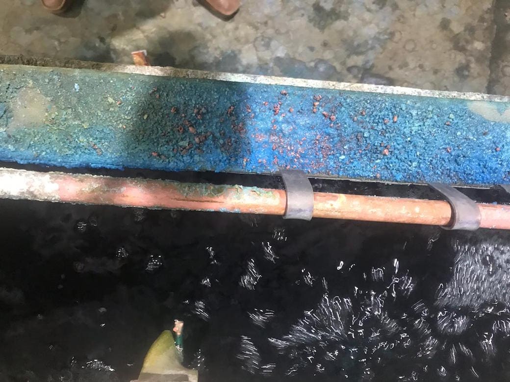
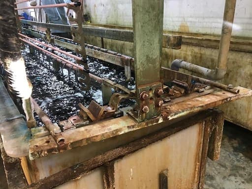
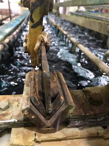
Deposition on Anodic Path
Deposition on Anodic Path
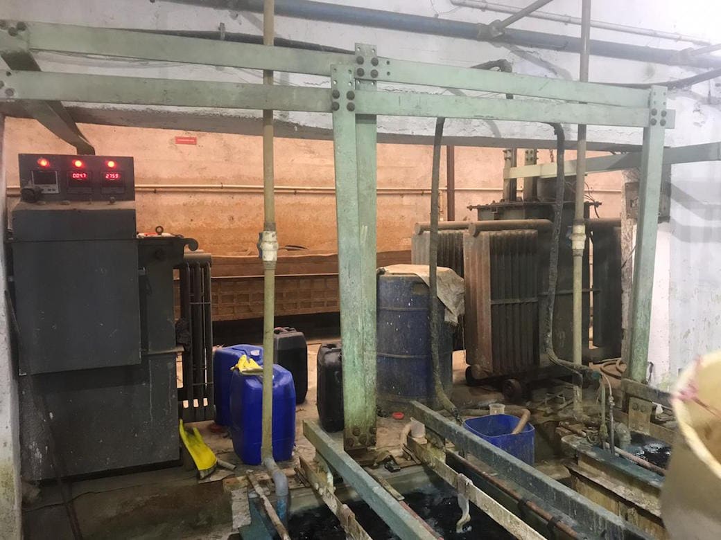
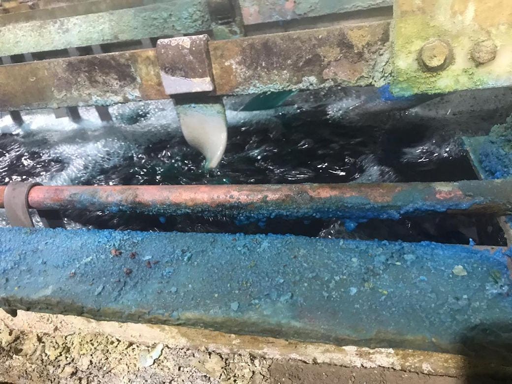
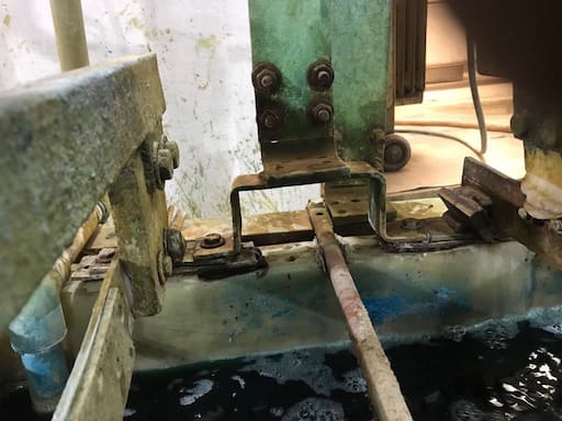
Rectifier to Tank connection
Rectifier to Tank Connection
Proprietor - Vadodara, Gujarat, India
A. Hi Tirath. First impressions:
1. You need a filter and anode bags
⇦ huh? rather than relying on the particulates to settle.
2. The deposition on the anode rods and tank rim is simply the drying out of splashes & fumes, and is not unusual nor the result of electricity.
3. The black jig needs to be stripped and re-coated with plastisol because the treeing is excessive.
4. The anode rods look too small to carry the current. Do they get quite hot? What is their ID/OD and how much plating current is used per tank or per rod?
Regards,
Ted Mooney, P.E. RET
Striving to live Aloha
finishing.com - Pine Beach, New Jersey
Need quick confidential answers? $25
Need project assistance? $100/hr.
November 2018
Q. Hello Ted,
Appreciate your prompt response.
What do you think about my specific questions, can we find any solution to that?
Coming to your question, the rod dia varies from 8 mm to 32 mm and the length varies from 1 m to 3 m
One question I have to your 2nd Point is that does the "drying out of splashes and fume" affect the conductivity in the anodic rack?
Thank you
Manufacturing - Vadodara, Gujarat, India
November 29, 2018
A. Hi again. What I was getting at was that, from a quick look at a picture, your anode rods look quite small to properly carry the current -- which would result in the poor plating distribution problems you describe. Copper can only conduct 1000 Amps/inch2 (1-1/2 Amps/mm2). That is why I was asking whether they were hot (indicating overloading), and how much current they must carry, and their OD and ID dimensions -- in your last picture they look to me to be hollow bars, but I can't see things well enough to figure out what that "W shaped" support or connection is. Maybe it returns power from the outside anodes to the more heavily loaded middle anode?
Accumulated stuff on the anode rods does not affect their ability to carry electricity through them, but it does affect the contact resistance where the anode hooks make contact with the anode rod. All contact point of all electrical circuits must, of course, always be free of any tarnish or trash. Contact surfaces like your anode hooks really ought to be "knife-edge" rather than long flats.
But what is puzzling me about your questions is that this is obviously an old and well-established plating line. Did it never produce satisfactory work in all its history? Or is this a new product line which you are trying to plate? Or have specifications tightened up on the product? Or did it once work fine but now inadequate maintenance and/or loss of experienced operators is now causing problems? In other words, what has changed that makes an old established plating line no longer satisfactory? Step one in the trouble-shooting exercise is usually to ask what has changed :-)
Regards,
Ted Mooney, P.E. RET
Striving to live Aloha
finishing.com - Pine Beach, New Jersey
Need quick confidential answers? $25
Need project assistance? $100/hr.
November 2018
December 3, 2018
Q. Dear Ted,
The total current coming out of the rectifier is 2800 A, which is distributed to 2 tanks, which is thereafter distributed to 2 cathodic racks per tank.
The size of the conductor from rectifier to tank - 70mm (W) X 10mm (T) ~ 4 A /sqmm. We are now distributing individual connection to the tanks from the rectifier itself with each conductor carrying 1400 A with the same conductor size. Hence we will achieve 2A / sqmm.
This Anodic conductor is a pipe with OD 20mm and ID 12mm and L 3962mm. The W shaped connection acts as a connector for the conductor from the rectifier to 3 individual anodic conductor.
The cathodic conductor is of size 50mm (W) X 6mm (T) on which the Jigs holding the articles is put, the jigs are made of pure copper of the same size as that of the conductor.
The anode basket
⇦ huh? are made of titanium and so are their hooks. Size - 15mm (W) X 2mm (T).
Over heating - Yes for all conductors
Observation : The first 2 and the last 2 articles on the jigs get faster deposition than the middle 4. And the jigs closer to the rectifier gets faster deposition than the ones away from it.
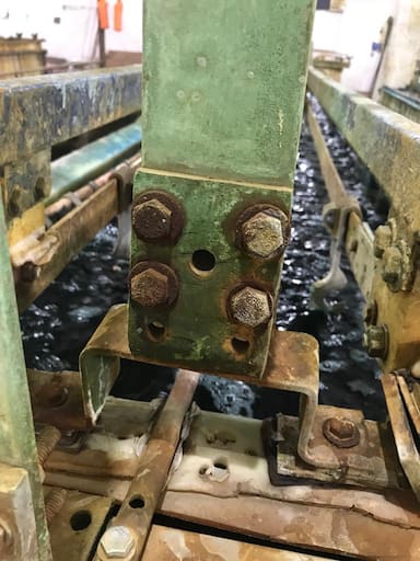
Attach : Pics of Conductor Joints and connections:
This has been an old problem which we have been curing by reworking the articles that have not received the amount of coating required.
Now, we are looking for a permanent solution to this that frees us from the reworking.
Thanks,
Manufacturer - Vadodara, Gujarat, India
A. Hi again Tirath. Doubling the main conductor from the rectifier was a good first step and, although 2 A / sq mm is still more than the 1.5 A / sq mm that we'd like to see, at least the overload is not outrageous :-)
Each load bar carries 700 Amp, so it should ideally be not less than 450 sq mm if bussed from one ends or 225 sq mm if bussed from both ends; it's actually 300 sq mm.
But the anode rods, at 50 ^200 sq mm, are overloaded (as we can see from the melted polypropylene). The center anode in each tank must carry 700 Amps whereas the rod would be appropriate for 75 ^300 Amps if bussed from one end. When tanks are bussed from only one end, the cathodes should be powered from one end of the tank and the anode rods from the other to help distribute the power.
Please retain the services of an electrical engineer or plating equipment engineer to review the whole system and guide in an upgrade. You may have other problems with this line as well, but you'll never get uniform plating thickness when the DC bussing is so terribly overloaded. Good luck.
Regards,
Ted Mooney, P.E. RET
Striving to live Aloha
finishing.com - Pine Beach, New Jersey
Need quick confidential answers? $25
Need project assistance? $100/hr.
December 2018
December 3, 2018
Q. Dear Ted,
Thanks for your constant support.
These are a below questions I have :
A. What do you mean by single end bussed and double end bussed? Does it mean if the conductors are stretched to both the ends of the tank to make an electrical connection?
What is the best electrical connection suggested for an electroplating tank which required utmost precision in the deposition amount, rate and uniformity.
B. How do I get the equal current distribution between the different articles in a different position on the vertical jigs?
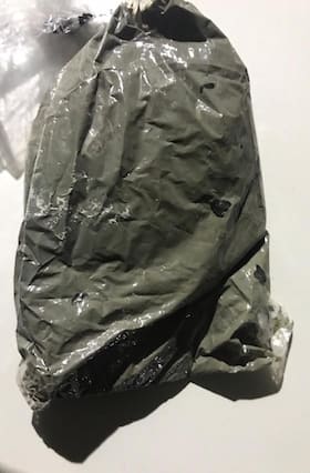
C. What kind of anode filter bags would you recommend to prevent such sludge from forming on the base of the tank (Pic attached).
We are currently making changes in the tank as we are receiving your valuable feedback.
And a genuine thanks for helping us out here.
- Vadodara, Gujarat, India
December 2018
A. Hi Tirath. Myself and other readers are always happy to help with questions, but that help cannot extend to trying to remotely supervise the redesign of a plating line -- that's a job for an on-site paid plating equipment consultant, like one of those whose support is helping make this site possible :-)
A. It is possible to run copper bus bar from your rectifier to the anode rods and cathode saddles at either end of your plating tank or to both ends. If that bus bar connects on both ends of the plating tank, then the anode rods and work bar only need to carry half of the current they have to carry if bussed from only one end.
B. I ducked that question because as long as you have grossly inadequate bussing and anode rods totally wrecking the current distribution, trying to account for more localized unevenness in current distribution is a fool's errand. But your plastisol coated jigs need to be adequate size for the current they are carrying (they may be already); and the coating must be good as I already noted ... if the current is able to grow "trees" as on your black jig, it's stealing the current in a way which must be stopped rather than mathematically analyzed. After all that is done, you can look at the relationship between anodes and workpieces to see if some workpieces are too close or too far from the anodic current.

(anode bag pic courtesy of The Bangalore Paper & Pulp Mills)
C. Sorry, I don't know what you have sent a picture of, but anode bags are made of polypropylene cloth and look rather like a sock you put over the anodes and tie in place.
Regards,
Ted Mooney, P.E. RET
Striving to live Aloha
finishing.com - Pine Beach, New Jersey
Need quick confidential answers? $25
Need project assistance? $100/hr.
December 4, 2018
Q. Dear Ted,
These is a bit of more info regarding our plating unit, please do let me know if you think we are wrong somewhere here.
A. Plating Tank Size (LXWXH) in inch = 144 X 28 X 25
B. Electrolyte capacity = 1500 Ltr
C. Ampere Offered currently = 70 A / sqft of cathodic area.
D. Total Anodic Racks = 3
E. Titanium Baskets / Rack = 13
F. SA of Anode / Basket = 1.4 sqft
G. Total anodes qty (in kgs) = 350 Kgs
H. Anode to Cathode distance = 6 inch.
We want to increase the current flow to 150 A / sqft, are there any changes you would recommend that we need to make in the plating tanks?
- Vadodara, Gujarat, India
A. Hi Tirath. I'm not going to engineer a plating line for you in this forum; you need to retain a plating equipment consultant for the redesign :-)
But I think you're dreaming in hoping to copper plate at 150 ASF in a plating line of this sort. Please focus on the things you need to do to get this line running right rather than what you would need to do to get it plating at over twice the speed at which you're plating wrong :-(
Luck & Regards
Ted Mooney, P.E. RET
Striving to live Aloha
finishing.com - Pine Beach, New Jersey
Need quick confidential answers? $25
Need project assistance? $100/hr.
December 2018
Q. Dear Ted,
Ok. Im working on getting the outer electrical connection sorted first.
Wanted to know how did you work on to calculate the area of the anode rod as 50 sqmm. Note - OD - 20mm, ID - 12MM. What is the formula for this?
Also, now that we are arranging the electrical connection from scratch. Which one would you recommend, double end bussed or single end bussed?
Thanks
- Vadodara, GJ, India
December 6, 2018
December 2018
A. Hi again Tirath. Apologies, my calculation of anode rod area was wrong. I made the error of dividing by 4 twice instead of once in the formula OD2/4 - π ID2/4 which I didn't catch right away because I unfortunately don't visualize in metric.
When I started designing plating equipment 50 years ago as a fresh engineer, my employer and their competitors had already been using "1000 Amps/sq. in" for decades. Thousands upon thousands of plating installations have used it, and it results in no power distribution problems but no significant wastage (the bussing will get slightly warm but not hot). And it tracks electrical codes pretty well too.
As for what it means, it means the cross sectional area of the copper carrying the current should not be less than that. Any bus bar carrying 2800 Amps should be 2.8 sq in. in cross section or greater; any bussing carrying 1400 Amps should be 1.4 sq. in. or greater; any bussing carrying 700 Amps should be 0.7 sq. in or greater; any bussing carrying 350 Amps should be 0.35 sq. in. or greater.
Your work bars are carrying 700 Amps each if I understood correctly. Your outside anode rods (the ones next to the tank walls are carrying 350 Amps each, and your center anode rods are carrying 700 Amps each.
Bussing from one end is fine as long as the copper is big enough, and the cathode saddles are kept clean, and the anodes are bussed from the opposite end of the tank than the cathode saddles are bussed from. Bussing anodes from one end and cathodes from the other is simple and cost effective, and means that the voltage from anode to cathode remains exactly the same along the length of the bars instead of being slightly higher at one end due to the resistance loss in the copper.
In terms of practical solutions rather than perfection, I would probably move the anode connections to the far end of the tanks, and either replace the center anode with a solid 25 mm dia. bar or squeeze in a second 20 mm OD x 12 mm ID anode rod.
Best of luck.
Regards,
Ted Mooney, P.E. RET
Striving to live Aloha
finishing.com - Pine Beach, New Jersey
Need quick confidential answers? $25
Need project assistance? $100/hr.
A. Hi Tirath
Before you get involved in technical solutions to your distribution problem there is a much more pressing matter.
From your photographs your connections to both anode and cathode are in terrible condition. It seems unlikely to me that the current is going where you may think it is and certainly not evenly distributed.
All bars and every contact point should be perfectly clean and show shiny copper. They look as if they have not been cleaned for years ! Operators must be trained to clean contacts as standard practice.
I can see that you have air agitation but it is so strong that it is adding to your problem, I would turn it down considerably.
Anode bags will not help distribution but will avoid much of the sludge. A good filter pump should also be a standard item.

Geoff Smith
Hampshire, England
December 6, 2018
Q. Currently the busbar connecting the positive end of the rectifier is connected to a plate which is further connected to all three anode conductors. So there is an equal distribution among three rather than the one you mentioned. Is an ideal situation what you suggested (Centre - 700 A, Side - 350 A each) ?
Also, is there any equation between the qty of electrolyte solution, qty of anode bars, qty of cathode bars?
- Vadodara, GJ, India
December 8, 2018
I did the calculation as per Faraday's law,
Currently at 6750 A Hr. our tank deposits 7040 gms weight of copper. Which accounts to 85.3% efficiency at what we are currently running.
Our current Anode to Cathode distance is 6 inches. So do you think we still have space to shorten the distance between anode and cathode such that the efficiency increases?
Note: We presently do not have a uniformity as we desire. Coating of 0.25 mm copper on MS rod of length 1.5 mtr results in some point with copper thickness 0.26 mm and some point with 0.18 mm.
Additionally, depending on its placement on jigs, some rods in the middle get 0.38 mm coating and the one on the top and bottom get 0.18 mm coating.
So we want to achieve lower resistance along with a uniformity along the length of the rod and across the various rods hanged on the jigs.
- Vadodara, GJ, India
December 8, 2018
|
A. Respected Ted, I really appreciate your efforts. You are spoon feeding Mr. Tirath. You & Geoff have given him the best possible answer. Now let Tirath work by himself. Sorry,if you feel my response to be arrogant. Avinash Vidhate- Nashik, Maharashtra, India. December 14, 2018 Hi Avinash. Your many responses have helped readers on this site often, so thank you as well. Everyone is welcome to continue posting their questions here, but I responded to this subject 6 times, continually stating that I will not undertake the detail engineering required for this reworked DC electrical distribution system, yet the questions continue in that vein; so, yes, people must either follow my repeated advice to retain a plating equipment consultant or do it themselves. Regards, Ted Mooney, P.E. RET Striving to live Aloha finishing.com - Pine Beach, New Jersey Need quick confidential answers? $25 Need project assistance? $100/hr. December 2018
- Vadodara, Gujarat, India December 19, 2018 Ed. note: This RFQ is outdated, but technical replies are welcome, and readers are encouraged to post their own RFQs. But no public commercial suggestions please ( huh? why?). |
Q. I am trying to electroplate silver on copper sheet of dimensions 6" x 6" with 0.5 mm thickness. We are using cyanide silver plating bath with masking on plate on one side. I am unable to get uniformity in my plating thickness. My uniformity tolerance range is 15% maximum. Can anyone suggest any solution of this problem.
ABHISHEK KALIAElectroplating Technologist - New Delhi India
February 23, 2023
A. Hi Abhishek. The abstract question of plating thickness uniformity has been addressed exhaustively on these 2 long pages over a period of 24 years now, so I don't think there's much point in simply starting over and repeating all of those abstract ideas again, from addition agents to temperature and current density control, to shields, to shaped or auxiliary anodes, to spinning the part during processing, etc.
Rather, I think we need to delve into the very exacting situation confronting you ...
Are you plating one single 6" x 6" piece at a time, or are you talking about a rack full of such parts? Can you provide a photo of what you are doing, and tell us the temperature, solution concentration and current density? Can you give us some hints about the thickness problems you are actually experiencing ... is the plating thicker on the top, on the bottom, on all 4 edges, in the middle, or totally random? Are you saying that your current thickness variation is 15%, or are you saying that is your target? If that's your target, what are you currently getting? Thanks!
Luck & Regards,
Ted Mooney, P.E. RET
Striving to live Aloha
finishing.com - Pine Beach, New Jersey
Need quick confidential answers? $25
Need project assistance? $100/hr.
Sorry! Finishing.com is temporarily Read-Only.
Ted Mooney is retiring but I have several offers to take it over.
We're working hard to make sure we find it the best new home.