
Home of the world famous 'finishing.com HOTLINE' since 1989
-----
Copper Bus Bar Sizing for DC low-voltage high-amperage
⇦ Tip: Readers want to learn from your situation;
so some readers skip abstract questions.
Q. Hi. How would you calculate the length and hole spacing required for a 2000A busbar at 48VDC if using 1/2" x 4" busbar?
TJ Jones- Lindon, UTAH
June 10, 2021
A. Hi TJ. Please introduce yourself and your situation. I assumed you were inquiring about the open bus bar systems typically used in electroplating, anodizing, and other metal finishing shops to bring DC power to the tanks, such as illustrated in the "Anode and Cathode Rod and Bus Systems" chapter of The Electroplating Engineering Handbook -->
but after looking up your company, I don't think that's the case, and what you will read on this page may be misleading :-(
Sorry, I don't know the answers for your situation.
Luck & Regards,

Ted Mooney, P.E. RET
Striving to live Aloha
finishing.com - Pine Beach, New Jersey
Ted is available for instant help
or longer-term assistance.
June 2021
Q. Hi Ted.
This would be for a DC combiner with a positive and negative bus to combine lithium battery banks and which would be the common point to power a whole lot of 48V inverters as a large energy storage system/UPS. My amperage requirement is only 1500A, but I've overspec'd for heat, losses etc in the system. So basically I will be making up the busbars myself with a whole lot of 3/8 bolts. I just want to make sure I keep to the correct PCD for the bolts as to not affect the load capacity of the busbar negatively.
- Lindon, Utah
June 10, 2021
⇩ Related postings, oldest first ⇩
November 18, 2008
Q. Hello all,
I'm a new plating learner.
Now I have a rectifier which the rating the output rating is 12VDC, 4000A. The current size of copper busbar which link from rectifier to chrome tank is 12 mm x 100 mm. To me, I think it is under size since the current ampacity of it should be around 2600A (in AC, DC should be less). My question are:
1) What is the actual size of busbar I have to use in this case?
2) How to calculate for DC busbar?
3) Will the size be different for DC and AC 50 Hz? In same current, copper which apply to DC circuit should be larger than AC 50Hz circuit?
Thanks
plating learner - Malaysia
A. This link should give you all the info you need.
www.stormcopper.com/design/Buss-Bar-Ampacities.htm
- Inman, South Carolina
November 24, 2008
A. Thanks, Kurt. I think that page should be fine for AC current calculations.
For DC bussing for a rectifier, however, I think the standard number used for decades, 1000 amps/square inch for open air bussing, is an easier and safer approach.
Khor, for an electroplating bussing installation I would consider the ampacity of a 12 mm x 100 mm busbar (slightly under 1/2" x slightly under 4") to be about 1860 Amps. You need at least two, not one, 12 mm x 100 mm busbars, although most experienced installers would probably use four or five 6 mm x 100 mm bars instead. Aren't the connections coming out of the rectifier implying that four or five 6 x 100 mm bars are suggested?
Regards,

Ted Mooney, P.E.
Striving to live Aloha
finishing.com - Pine Beach, New Jersey
Ted is available for instant help
or longer-term assistance.
November 24, 2008
December 5, 2008
i. Ted
I have never claimed to be an electrical engineer, but have run a lot of wire in my day. I never considered that there would be a difference in ampacity for AC vs DC. I reached out to the folks at Storm Copper for validation. My question was very simple:
Is there a significant difference between AC ampacity and DC ampacity?
There response was:
Yes. DC causes greater heating of the bus. I believe de-rate AC values around 30%.
A quick study of their ampacity tables complicates the issue even more. a 1/2" x 2" buss is listed at 1000 amps. Fits your number perfectly. A 1/4" x 4" buss however is at 1250 amps. Maybe more heat transfer area to keep it cool.
However, Storm is suggesting to derate the AC by 30% for DC current meaning those two bars would be 700 and 875 amps.
- Inman, South Carolina
! Thanks again, Kurt. I've been sizing DC bus bar the same way for 40 years, so I would dearly love to get out of that rut and hear a newer and better way. And I understand that a 1/4 x 4 bar has greater surface area and cooling, and consequently higher current carrying capacity, than a 1/2 by 2 bar.
But the fact is, 1000 Amps/sq. in has proven itself for decades. If these charts indicated higher ampacity than the simple old-fashioned method, I'd want to go along with them. To the degree that they suggest that copper can only carry 70 to 87 percent of what we know for a fact that it has safely and reliably carried in tens of thousands of plating and anodizing installations over 5 or more decades, I think it is they who need to go back to the drawing board :-)
Their figures may be for bus bars enclosed in power distribution boxes or bus ducts rather than out in the open air.
Regards,
Ted Mooney, P.E.
Striving to live Aloha
finishing.com - Pine Beach, New Jersey
Ted is available for instant help
or longer-term assistance.
December 15, 2008
Q. Hi, just wondering whether anyone can help decide proper size of a conductor. This is specifically regarding hard chrome plating but can be applied to other types of plating as well. We use rectifiers that generally operate 7-9 V and about 1500-2000 A. They are connected to the plating tanks with solid copper bars. Parts are hung in the tank using steel fixtures with copper strips to aid the current flow as far as it is possible. We do not generally like the copper to come in contact with the plating solution. Our maintenance people make the fixtures, but sometimes they are not sized properly so they overheat and parts end up at the bottom of the tank. I would like to be able to size the fixtures and other conductors properly so that we avoid the failure problems and improve the efficiency of our plating in general. I have had a hard time finding information regarding this. How can I calculate how much current can I send through a solid conductor? I understand resistivity of metals increases with temperature and that I can decrease resistance by increasing the cross section of the conductor, but how do I know at what temperature (resistivity) will the conductor arrive if I send a given current through it? Are there any tables of recommended solid conductor sizes for dc current similar to what is used for home wiring? I will appreciate any help you can provide. Regards, P Marek
Petr MarekPlating shop owner - Vsetin, Czech Republic
March 16, 2009
A. Hi, Petr. As you see, we appended your inquiry to a thread which I think will answer it for you: the copper needs 1 inch of cross sectional area for every 1000 amps. Good luck.
Regards,
Ted Mooney, P.E.
Striving to live Aloha
finishing.com - Pine Beach, New Jersey
Ted is available for instant help
or longer-term assistance.
March 19, 2009
Q. Thank you very much for your post. I have a follow up please, what about fixtures for hanging the parts in the tank? When we do inside diameters or fixtures that require a threaded bar, we use steel to support the mass of the part(s). How can I determine the resistance of the fixture when I have no idea about its temperature? In other words, how large does the cross section of the steel fixture have to be in to facilitate proper current flow or at least so that it does not overheat and fail mechanically.
Petr Marek [returning]- Vsetin, Czech Republic
March 19, 2009
A. Hello again, Petr. Steel is an alloy, and the conductivity of alloys varies very widely, with some stainless steels being only 3 percent as conductive as copper, and some plains steels close to 15 percent, so it's hard to put a perfect number on this. But figure it is about 10 percent of copper. That means I'd go with 100 Amps/sq.in. when submerged, even if the particular steel were a little lower in conductivity.
Obviously, this is a suggestion only applicable to submerged plating jigs, and not to be extrapolated that it's okay to figure steel as 10 percent of copper in all applications :-)
Regards,
Ted Mooney, P.E.
Striving to live Aloha
finishing.com - Pine Beach, New Jersey
Ted is available for instant help
or longer-term assistance.
March 20, 2009
![]() Thank you for your help Ted.
Thank you for your help Ted.
- Vsetin, Czech Republic
March 27, 2009
Q. DC resistance of copper bus bar. I want to measure the end resistance and inductance of a bus bar. Which methods I can apply to do the same. Suggest me the methods of measurement of the resistance and inductance of a copper bus bar.
Thanks & Regards,
product designer - Hyderabad, A.P., India
March 29, 2011
A. Hi, Suresh. To measure the resistance of a bus bar you can use Ohm's Law. Back when I was in school it was R = E / I, today you probably hear it as R = V / A. You simply measure the voltage drop while the bar is carrying a known current.
DC currents have no inductance; inductance is the voltage induced rather by a non-steady-state current. L = E / (dI/dt)
Regards,
Ted Mooney, P.E.
Striving to live Aloha
finishing.com - Pine Beach, New Jersey
Ted is available for instant help
or longer-term assistance.
June 2011
Q. Hi to all, I want to know all types of Copper bars Current calculations. For example, For 1500 Amps Which size Copper Bars I have to use Terminal box i.e. free & open in air. And also I want Aluminum Calculations also.
M NareshTransformers - Mumbai, Maharashtra, India
June 27, 2011
Q. Hello, I need to know the calculation for DC bus bars Size for Copper and Aluminium.
Sujin SreedharanMachines - Mumbai, Maharashtra, India
April 12, 2012
A. Hi, Naresh. Hi, Sujin. Please get tables from suppliers like stormcopper or consult the National Electrical Code. Aluminum bus bar seems to be rated about 50 to 60 percent as conductive as copper.
But please keep the discussion moving forward by trying your very best to phrase ongoing questions in terms of the answers that have already been offered. If you didn't understand something and want clarification, that's fine -- people will try explaining it in different words ... but few readers will even read let alone try to answer a question that was already answered and is then simply repeated :-)
Regards,
Ted Mooney, P.E.
Striving to live Aloha
finishing.com - Pine Beach, New Jersey
Ted is available for instant help
or longer-term assistance.
April 12, 2012
Q. How to calculate copper bus size for the Continuous DC load of 100A & a peak load of 200A for 1 Sec. Please advise criterion for the selection of DC bus size for the peak loads.
Hitendra Shah- Abu Dhabi
April 15, 2012
A. Hi, Hitendra. Good question. I've used 1000 Amps / square inch (in open air) in plating and anodizing shops for many decades, so I think 1/10 of a square inch would be correct for 100 Amps continuous load. But unfortunately I have no actual experience in short peak loads, so I can't answer from experience. I think the correct answer will be slightly more than 1/10 of a square inch for a peak load for only one second, but I can't say for sure, and feel that the codes probably want you to size things based on maximum-ever loads for safety, not usual loads. Hopefully someone who knows will help us.
Regards,
Ted Mooney, P.E.
Striving to live Aloha
finishing.com - Pine Beach, New Jersey
Ted is available for instant help
or longer-term assistance.
April 16, 2012
Q. In Electrorefining they typically use triangular busbars, where the header bars of the cathodes and anodes go across these busbars, and only touch the top edge of the triangle. There is a resistance due to the contact of the two pieces (header bar-busbar) and this can be calculated using Holm's equation (is an inverse function of the square root of load), however I have differing ideas in how to calculate the resistance through the buswork (through the triangular bar) as the contact is initially on the edge, rather than the end of the triangle.
As R=rho*length/Cross-Sectional Area wouldn't there be a high amount of resistance near the joins due to the area being so small (as the contact is on top resulting in an edge contact, rather than contacting the entire cross-section at the end)? Some electrical people I talk to say DC current is like water, so that you can use the entire cross-section of the triangle as it is like spilling into a tank, but what about the other end? Then it will want to bank back and be a massive resistance as its going back into a very small area? Any ideas would be welcome. I have been going back and forwards with this for weeks.
I am not an electrical person, a mechanical person and it would seem to me to be a fundamental electrical problem, yet I cannot find any information anywhere.
Thanks.
- Brisbane, Queensland, Australia
May 31, 2012
A. Hi Chris.
I can't exactly answer your inquiry, but think of this: when two flat surfaces of say 1" x 1" contact each other, we might say that the contact area is one square inch, and the DC ampacity of the joint is therefore 1000 Amps. But if you were to look at that contact surface through a powerful microscope, you would see that only very small peaks and very limited areas are actually touching. We still say the ampacity is 1000 Amps; we don't calculate a reduced capacity based on the smaller contact area we see in the microscope. That is, we have a macro thumb-rule that a square inch of copper can carry 1000 Amps, and we don't apply that macro rule to a micro situation. I think that's the case with the triangular bus bars, which are intended to deliver a knife-edge (and therefore better) contact surface.
I think that we can see from Ohm's Law that the knife-edge contact is not causing a significant resistance, and we can see (with a thermal scanner if not by hand) that there is no dangerous heat buildup at the knife edge. To me, that's the end of the analysis, the ampacity of the contact is based on the cross sectional area of the bus bar or the header bar, whichever is smaller.
Note to readers: The internet is a giant one-room schoolhouse where you can "overhear" stuff and misapply it; I'm talking about copper bus bars carrying DC current in electrowinning operations; I'm not offering a general theory applicable to all electrical contact surfaces :-)
Regards,
Ted Mooney, P.E.
Striving to live Aloha
finishing.com - Pine Beach, New Jersey
Ted is available for instant help
or longer-term assistance.
June 1, 2012
Q. Hi
Related to the thread, if I intend to use DC cables instead of Copper Bar for connecting rectifiers to the anode and cathode bars, how should I go about deciding what size and kind of cables to buy.
And would it make any difference if use cables instead of copper bars. As in whether it is better or worse.
Would appreciate some help.
Thanks and Warm Regards
Sunny
plating on plastics - New Delhi, India.
July 6, 2012
A. Hi Sunny.
Cables are widely used in plating shops. Although it's true that the insulation may make them get somewhat warmer than an open bus bar, I've never personally seen a problem if the old thumbrule of one square inch per 1000 amps of rectifier capacity is used. Welding cable is often used because it's both flexible and designed to carry substantial currents.
Regards,
Ted Mooney, P.E.
Striving to live Aloha
finishing.com - Pine Beach, New Jersey
Ted is available for instant help
or longer-term assistance.
July 2012
Q. My existing plating tanks have undersized cathode bars (3"x .75", 4000A rectifier) which cannot be upsized. During plating the cathode bar gets so hot you cannot touch it. Currently, bussing is only connected to one end of tank. Will connecting both ends of the cathode bar decrease the resistance through the cathode bar to the 40 plating racks evenly spaced on the bar? Does this essentially double the current carrying capacity of the cathode bar (almost like having 2 shorter cathode bars end-to-end each with 2250A current capacity)?
Joe Smithchrome plater - Portland, Oregon
September 24, 2012
A. Hi Joe. Yes, exactly. This will work, and it should be done immediately before you risk catching the tank liner on fire. Don't forget to check the ampacity of the anode rod when you fix the cathode rod.
Regards,
Ted Mooney, P.E.
Striving to live Aloha
finishing.com - Pine Beach, New Jersey
Ted is available for instant help
or longer-term assistance.
September 24, 2012
Are my bus bars properly sized?
May 28, 2015Q. Good Morning
I need to reinstall some bus-bars in our factory.
Distance from rectifier to tank is 10.5 m.
I order 38 x 6 mm copper bus-bar / line.
Maximum current 400 A on 8 ~ 10 V DC.
It is enough dimension for new copper ?
Old bus bars are 52 x 14 mm (installed maybe 40 years ago). I cannot reuse them and I don't want to. There are too heavy and dirty.
Best Regards
Mike
- Walton On Thames, Surrey, UK
A. Hi Mike. If there is something you don't understand on this page, we'll be happy to try to explain it in different words until it is completely clear. But the voltage has little to do with it (in this limited context of bussing a plating tank that operates at the usual industrial levels). The length of the run is not totally irrelevant, but for typical plating shop runs, like 10.5 m, it's not real important. My own thumb rule, which was already a well established guideline at the plating equipment manufacturer I went to work for in 1967 is simply 1 square inch (645 square millimeters) of cross sectional area in the bus bars for every thousand amps you want to carry. This gives you measurable but not excessive voltage drops, and warm but not hot bus bars. So you would need 645 * 400/1000 = 258 square millimeters, and you've only got 228.
My opinion, and that's all it is, is that you should have ordered 6 mm x 52 mm (1/4" x 2") bars. The rectifier terminal often implies what size bus bar the rectifier manufacturer feels is appropriate. But whether you should proceed or start over may be a different question, and I suspect that most people would advise you to just continue :-)
Regards,
Ted Mooney, P.E.
Striving to live Aloha
finishing.com - Pine Beach, New Jersey
Ted is available for instant help
or longer-term assistance.
May 2015
May 29, 2015
A. Good day Mihai.
Ted has a good point about the calculations, but this is not written in stone. Your busing is 12% short of IDEAL calculations. I feel you can proceed with what you have.
I would, however, like to make a suggestion.
If you are leading each end of your cathode/anode bars from the MAIN busbar, I found that these leads from the MAIN busing should be of the same length.
You can measure the amperage along the length of the cathode bar on each rack/fixture with a tong tester/ammeter to verify the amperage is consistent.
Hope this helps.
Regards,
Lab Tech. - Whitby, On. Can.
Q. How to calculate the copper busbar size for a given DC current rating ?
I have a rectifier it gives output 24 volts DC and 15000 amps at source to load in distance 6 m, 5 m, 2 m, 1 m. At what size of busbar(or) cables are taken my application and what type of insulation I prefer to the bus bus at safe conditions.
I don't have any knowledge of busbar size calculation; please send me choice of a correct busbar sizes for required current rating.
- Hyderabad, India
September 19, 2015
A. Hi Shiva. I think you may need to retain an experienced electrician, electrical engineer, or plating consultant -- someone who has worked with this stuff and is familiar with the concepts being discussed. How to size this stuff has been explained numerous times just on this one thread alone, and if you can't follow it sufficiently to do the arithmetic yourself, you don't understand enough to install bus bar without guidance. Although voltage drop is proportional to the length of the bus bar, it's not conventional to use different cross-sections of bus bar for lengths of 6 meters vs 1 meter.
Safety issues are tricky at best. Is this a manually operated installation? I am long familiar with open bus bar systems which have no insulation at all, and which have been used for many decades in plating shops -- but I've also seen movement toward people no longer accepting open bus bar systems as being safe, especially as we get to higher voltages like 24 V. Welding cable sized at 1000 Amps/square inch can be used as an alternative to open bus bar, but doesn't fully address the issue of people working with live 24 v systems. A metal tool accidentally shorting out a 15,000 Amp power supply can be a spectacular event! In any case, you obviously should minimize potential exposure to live circuits even though they are only 24 V, and people in the area should clearly understand the situation. Sorry that it's hard to be of much more help from such a distance.
Regards,
Ted Mooney, P.E.
Striving to live Aloha
finishing.com - Pine Beach, New Jersey
Ted is available for instant help
or longer-term assistance.
September 2015
Q. Thank you for very useful information; I have question as I work only in AC and I'm managing project for DC busbar with the following data: length 100 m, Current 2000 A, Voltage 48 V, size 1600 mm2. After calculating voltage drop (V 10.2, please correct me if I'm wrong) the loss in voltage first will result in not getting required voltage at the bus end and heat dissipation will be high (about 20.4 KVA again correct me if I'm wrong) even if I adjusted the source voltage to compensate for the voltage drop the heat is high. and as stated above it's in line with 1000 Amp/sq.in. Please advise.
Thank you
- Melbourne, Florida
November 4, 2015
A. Hi Khaled. The resistance of the bus bar is calculated as: R = ρ x l / A
The resistivity of copper bus bar is about 1.68 x 10⁻⁸ ohm-m, so I get as the resistance of your bus bar:
1.68 x 10⁻⁸ ohm-m x 100 m / (1600 mm2 x 1 m2 / 1,000,000 mm2), so:
R = 1.05 x 10⁻³ Ω
And V = I x R, so I get:
V = 2000 A x 1.05 x 10-3 Ω = 2.1 Volts
That's a lot, and it would apply to each pole if they're both 100 m long. Then again, 100 m is pretty long for a DC bus run.
The KVA waste sounds like 2000 A x 2.1 V /1000 = 4.2 KVA.
Regards,
Ted Mooney, P.E.
Striving to live Aloha
finishing.com - Pine Beach, New Jersey
Ted is available for instant help
or longer-term assistance.
Q. Hello dear Ted,
I have a question for you: what's the whole voltage drop, cross section and short circuit current computing procedure of a DC busbar?
For example: A DC busbar with 38000A current, 200 v dc
Sincerely yours,
- yazd.iran
January 16, 2016
A. Hi cousin Hojat. Sorry, but we'd just run in circles and never get anywhere if, after 30 postings on a subject, instead of asking for specific clarifications people just say "start over and tell me everything" :-)
I don't see how the voltage drop and cross section calculation you wish to do is any different than Khaled's example which I just worked for you. Sorry, I don't know the codes regarding short circuit protection (if any) in your situation, and my main experience is with low voltage busbar, not 200 V busbar. Good luck.
Regards,
Ted Mooney, P.E.
Striving to live Aloha
finishing.com - Pine Beach, New Jersey
Ted is available for instant help
or longer-term assistance.
February 2016
Q. I am looking into the ratings for the Bus bar that is used on my anodizing tanks. I have always understood that the Rise in Celsius is the rise over ambient or resting temperature. I currently have 1/4" x 3" Buss bar on my tanks, which according to the charts, is rated at 1500 amps at a 65 degree Celsius rise? But I have not found a chart stating whether that is AC or DC. In stating that, my questions are simple. Using my current bussing, what are my limits on DC Amperage, and what is the temperature rise above ambient that I should factor in?
Thank You
- Thomasville, North Carolina, USA
May 3, 2016
A. Hi Danny. 1/4" x 3" bus bar is rated 750 Amps, not 1500 Amps, based on 1000 A/sq.in. If you are speaking of an anode rod or cathode bar on top of the tank, yes, it's capacity could be 1500 Amps if it is bussed from both ends (750 A coming in from each end).
Regards,
Ted Mooney, P.E. RET
Striving to live Aloha
finishing.com - Pine Beach, New Jersey
Ted is available for instant help
or longer-term assistance.
May 2016
Q. Is cable advisable to use for 700 Amps Oil Cooled rectifier for Nickel plating or it should be Copper bar only. And what should be the Jumpers sizes for carbon brush holders.
Also, How many carbon brushes to be used at each side. These are for rotogravure cylinder plating machines.
- Lagos Nigeria
February 14, 2018
A. Hi Anand. Sorry, I don't have any experience with carbon brushes, so you'll have to wait for input from others on that. I've already offered my opinion on cables and the sizing criteria I use twice on this page; maybe someone will offer a second opinion.
Good luck.
Regards,
Ted Mooney, P.E. RET
Striving to live Aloha
finishing.com - Pine Beach, New Jersey
Ted is available for instant help
or longer-term assistance.
February 2018
Protecting bus bar from corrosion in a plating shop
Q. Good afternoon. My name is drew and I would like to know if conductivity of copper buss bars degrades with the accumulation of green corrosion. And if this loss of performance is enough to change or clean the buss bar. I know that the surface corrosion will have a very small impact but that the connections could be significant. We electroplate zinc onto ordinary Link chain at 9 VDC @ 3000A. I have read your thread and would like to know what you have to say regarding the corrosion and its effect on conductivity as well as any experience you have with cleaning the buss bars and methods to minimize the accumulation of green corrosion. Are there ways to make the corrosion more manageable. Thank you in advance.
Drew
Apex Tool Group - York, Pennsylvania USA
March 9, 2018
A. Hi Drew. There should be no decline. I have seen plating shops clear coat or lacquer their bus bar runs (except for the connections of course) and it does seem to hold up well and to look better than streaky green stained copper.
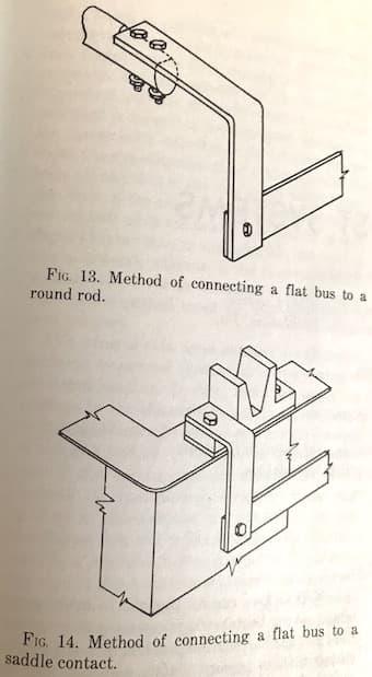
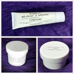
Bus bar connections are actually supposed to be silvered or tinned. I visited a GE or Westinghouse bus bar plant decades ago where they hung bus bar vertically and dipped it 4"-6" deep into the plating solution to plate the ends. Bus bars are also supposed to be clamped together rather than bolted, I believe. But in my own experience, plating shops rarely use plated ends or buss bar clamps: they just drill holes, and wire brush No-Ox-Id compound onto the joint area before bolting together. Good luck.
Regards,
Ted Mooney, P.E. RET
Striving to live Aloha
finishing.com - Pine Beach, New Jersey
Ted is available for instant help
or longer-term assistance.
Q. I made 200 amp switch with tin coated copper busbar. At 200 amps the joints are heating to 70+ °C.
What could the heating be due to?
All joints (male/female ) are firm and good contact.
- noida, up, India
January 8, 2020
A. Hi Ajay. Are all components at least 1/4" x 3/4"? There should be no spot on the switch where the cross sectional area of the copper is less than 1/5 in2 because the current carrying capacity of copper is 1000 A/in2.
Are you sure the copper is all hard drawn electrolytically pure? The current carrying capacity is drastically reduced with even a very small amount of alloying materials. Did you wire brush the joints and apply conductive joint compound?
Regards,
Ted Mooney, P.E. RET
Striving to live Aloha
finishing.com - Pine Beach, New Jersey
Ted is available for instant help
or longer-term assistance.
January 2020
Q. How to calculate DC bus bar current carrying capacity with respect to temperature.
e.g.: I have copper bus bar width = 14 mm, thickness= 6 mm, temperature 100 degrees -- so how to calculate current carrying capacity.
student - Bangalore,Karnataka, India
January 14, 2020
A. Hi Virendra. Generally, the allowable temperature rise is fairly low and it doesn't do much good to design to a higher allowable temperature rise anyway -- because conductivity is inversely proportional to temperature. So you will see that empirical numbers are used instead. Here in the USA and in the electroplating industry, the nice round number of 1000 Amps per square inch for open bus bar was universally accepted long before I entered the industry, and that was over 60 years ago :-)
The allowable current carrying capacity of enclosed bus bar in bus ducts is a little bit lower because of lack of cooling; since bus duct is a standardized product, you'll see the numbers in product literature and electrical codes.
According to my method, your 14 mm x 6 mm bar can carry 130 Amps in open air.
Regards,
Ted Mooney, P.E. RET
Striving to live Aloha
finishing.com - Pine Beach, New Jersey
Ted is available for instant help
or longer-term assistance.
January 2020
No dead threads!
Your Q, A, or Comment puts this thread on The Finishing.com HOTLINE.