
| Search our quarter-million Q&As |
Home of the finishing HOTLINE since 1989
-----Building a plating rectifier myself
Q. Greetings, I would like to commence by thanking all of you for your immediate and informative responses to all my questions over the past few months. I always try to read previously posted letters before I write my own, simply because I know it becomes tedious to answer the same questions over and over again. I haven't found what I was looking for in any posted letters, so here it goes.
I am trying to build a DC rectifier for some hobby-plating. I would like to convert regular household 120V AC into a variable controlled DC rectifier capable of 15V with at least 20 amp output. I've seen some prototypes for anodizers and plating rectifiers, however, I haven't come across any plans for one with sufficient amperage (>15 amperes). If there are any posted letters or electronics sites I could investigate, it would be a great help. Thank you all, and Thank you Ted, for answering my last question.
Frank B [surname deleted for privacy by Editor]- Toronto, Ontario, Canada
2003
Q. I have two questions:
Does anyone have a schematic to build a plating rectifier capable of plating parts up to approx. 100 /sq in
The next question is would it be possible to use the output from a high end DC TIG welder miller either straight or with modification to reduce the ripple ?
I know I'm going to get the reply "Why don't you just take it to a professional" Well I have two reasons one is that I'm curious in learning how to do it myself which I can't do if I take it to someone else. And the reason I'm doing it is this I have a whole machine shop full of equipment I purchased which was sitting and started to rust, I want to slowly in my spare time disassemble the machines repaint them and polish and plate the rusted parts so they will not rust easily. Yes I could look for a used unit but I would like to experiment cheaply in my spare time; I'm not looking to build a business or compete with any professionals nor do I believe I can do as good a job without professional equipment
Any constructive replies would be appreciated
Henry W [surname deleted for privacy by Editor]- Bensenville, Illinois
2004
A. Hi Frank; hi Henry. This question has been asked a few times here and remains largely unanswered -- probably not so much because anyone is hiding something, but perhaps because there has been no market for a hobby electronics magazine to develop an article on how to design & build something that few electronics hobbyists would have an interest in and would not have easy access to get parts for. Your best bet for a schematic might be a used plating equipment dealer who will probably have accumulated cartons full of instruction manuals detached from the rectifiers they go with; these will include the schematic diagrams you seek.
Another reason rectifiers can be harder to build than other electronic projects, is that the control circuits are not the heart of the issue; rather, big stuff is. Building a rectifier is not primarily about a control circuit, it is about large stuff that is hard to build yourself and can't be bought from radio shack -- like large transformers, chokes, heavy tap switches, high amperage diodes, etc. But if you can hold it to 20 Amps, maybe letter 12200 can help you. Good luck!
It works both ways, industry owes much to hobbyists -- plating rectifiers all operated at 60 Hertz until recently, but we learned from the personal computer industry, established by hobbyists, that much smaller and lighter power supplies can be built by "chopping" (interrupting the current flow in one way or another to generate much more than 60 Hertz). This approach was slow to penetrate the large rectifiers of the plating industry, but is fairly common now; they are usually called "switchmode rectifiers" in this industry. If you can get together a schematic for a switchmode rectifier rather than a conventional one, you won't need the huge components that are a plague to try to make :-)

Ted Mooney, P.E.
Striving to live Aloha
finishing.com - Pine Beach, New Jersey
Need quick confidential answers? $25
Need project assistance? $100/hr.
2004
Q. I certainly understand that a common electronics mag wouldn't publish this schematic however I certainly believe given the number of websites devoted to home plating supplies and the like there are great number of tinkerers that would be interested, I think I would say at this point if anyone has this interest and disregards the responsibility of using and disposing of the chemical waste properly please forget it. As far as obtaining the "Big" components I already have sources for these from the net their easier to find than the basic schematic for the rectifier. From reading the suggested article this unit develops 2.5 volts whereas 12 V seems to be the platers choice based on letters I've read here, Thanks anyone providing input.
Henry W [surname deleted for privacy by Editor]- Bensenville, Illinois
2004
A. I have had read several inquiries about home hobbyists wanting to build rectifiers, and their reasons are compelling (after all, plating is fun). But I have to agree with Ted; building a useful rectifier would be a large & complicated undertaking not suited for most home hobbyists. Besides, you do not need one!
All a rectifier does is convert AC to DC, preferably 12 VDC. A good source of 12 VDC current are deep cycle marine batteries. While batteries are not a practical option for plating shops, they are great for plating a part in the garage. Now having recommended batteries they are a few safety/technical issues one needs to know:
First: Do not use jumper cables, they spark! Marine batteries come with screw terminals, use them.
Second: Battery capacity is key, use two or three in parallel for longer plating times and/or larger parts. Also, you will need a good automotive battery charger
⇦ on
eBay or
Amazon [affil link]
to top off the batteries in-between cycles.
Third: You will need to control the current (look at the cranking capacity of your car battery, its huge!). I use a LARGE brush transformer out of an old oven power supply. Note, lots of current requires lots of copper or it results in lots of heat! Enough heat to melt metal and start fires.
Fourth: Measure the output! A good ammeter and voltmeter are important.
Finally, as with any home project, accidents can happen. The response that I have given is for informational purposes only.
Materials & Process Engineer - Lodi, California
Q. I require the electrical diagrams in order to construct my own electroplating rectifier.. Ranges between 1 to 10 volts and variable to 100 amps 240 Volts Single phase input.. Just basic plans required, will develop as project from there,,
Mike PretoriusEngineering and gunsmithing - Windhoek, Namibia
February 19, 2008
A. Hello Mike Pretorius. Just compare Electroplating to Electric welding --
Both work on the same principal "Low Voltage and High Amperage". Amperage is the Vehicle that deposits the Filler metal on the Cathode (collector).
To construct a Electroplating unit you require :-
(a) High wattage Step down Transformer 220 V/ 12 V
(b) Variac to control the input supply voltage
(c) High amp bridge rectifier to change AC to DC Diode rectifier
220 V supply ---> Variac ---> Transformer ---> Diode rectifier ---> pos/volt ---> Anode , neg/volt ---> Cathode.
You could take a DC welder with a Transformer and just control the input voltage with a variac/ potentiometer.
- Palm Springs California
?? Hello Mike Pretorius,
How about some feedback ... did you build your own electroplating rectifier? Did you follow my instructions?
I am amazed at the high prices for plating rectifiers.
Johan
- Palm Springs, California
September 27, 2009
A. The problem with using a variac is that very few of the windings are in use i.e. dissipating heat, when set to a low voltage that would be required for a plating rectifier. This could result in burning the variac windings if there is a high enough load.
Steve Gorzo- Calgary, Alberta Canada
November 1, 2012
Q. I have 5 (five) 300-amp MIG welding machines. Now I want convert this as a plating rectifiers. Anyone please give your valuable guidelines. Thank you.
Rajasekarengineering works - Hosur, India
January 11, 2013
February 6, 2014
Q. Regarding the answer by Johan Loots:
Can someone tell me why you need the transformer?
As I understand it, the bridge rectifier converts the AC to DC.
I also don't understand why the Variac is used before the transformer?
I admit I don't know much about rectifiers, but I am looking at the Specs for an RS 605 rectifier I pulled from a computer power supply ( http://pdf.datasheetcatalog.com/datasheet/RECTRON/RS604.pdf )
It says 50 to 1000 volts and 6 Amps.
It also states a low forward voltage but I can't figure how much it is.
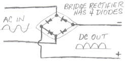
What happens if you simply plug the 2 AC leads on the Bridge Rectifier into a wall socket, and the 2 DC leads to your plater?
- New Rochelle, New York USA
A. Hi Gary. I don't know how to build a plating rectifier, but I can try to answer a couple of your questions.
House current is 110 or 220 volts, whereas plating voltage is more like 3 V to 12 V, so the transformer is what reduces the voltage to a usable range while also increasing the available current. If we leave aside and factor out the inefficiency of the transformer, it converts say 5 A at 220 V to 50A at 22 V. Although the phrase "isolation transformer" has been diluted a bit to where it is not a good specification, another important action of the transformer is to separate the output from the source to reduce high voltage shocks.
A bridge rectifier is simply 4 diodes to convert AC voltages to a series of "camel humps" rather than smooth DC current. Although professionals wouldn't attempt to plate with this output because it causes certain problems, so they would use an induction/capacitance "choke" to smooth it, a hobbyist could try without a choke, but with the bridge rectifier wired the way Johan describes. Wired your way, plugging the bridge rectifier into a wall socket, the voltage would be much much too high and there would be no isolation, and the likelihood of electrocuting yourself would be very high!
Actually, a Variac is a variable transformer. So Johan is suggesting a fixed step down transformer from 220 V to say 22 V, followed by a variable transformer to get from, say, 22 V to the variable plating voltage.
Regards,
Ted Mooney, P.E.
Striving to live Aloha
finishing.com - Pine Beach, New Jersey
Need quick confidential answers? $25
Need project assistance? $100/hr.
A. I designed a variable voltage DC linear power supply for powering ham radio equipment that may fit the bill for up to about 35 amps in the way that I built mine but with the linear regulators I used it is scalable by using more or less regulators with a maximum of up to 9 amps per regulator chip. I haven't tried to use this for electroplating yet but I may bring it to the shop the next time our zinc rectifier goes down.
**Note, there are certain safety measures designed into modern power supplies and rectifiers that are not featured in this design so use at your own risk.**
You can see the design and schematic by watching this video.
Read the schematic for the linear regulator you choose to learn how to run several regulators in parallel and as Ted said, it is not a matter of building a control circuit it is a matter of having heavy duty components that will withstand the high current draw of electroplating.
- Calgary, Alberta, Canada
October 9, 2015
A. I bought a bridge rectifier from amazon for $3.35.
"400V 25A Bridge Rectifier"
Unless you have your own parts to build one from diodes, in which case just use Mr. Mooney's diagram, I'd say that price can't be beat.
- Clearwater, Florida USA
October 9, 2015
Steve G. wrote: "I designed a variable voltage DC linear power supply for powering ham radio equipment that may fit the bill for up to about 35 amps in the way that I built mine but with the linear regulators I used it is scalable by using more or less regulators with a maximum of up to 9 amps per regulator chip. I haven't tried to use this for electroplating yet but I may bring it to the shop the next time our zinc rectifier goes down."
I would love to ask Steve Gorzo if he got a chance to try his linear power supply out on electroplating and if so did it work? Also, I would appreciate help in building my own. I have several parts from things I have salvaged parts from, like Microwave ovens and stereo components.
- Clarinda, Iowa, USA
January 29, 2018
Sorry! Finishing.com is temporarily Read-Only.
Ted Mooney is retiring but I have several offers to take it over.
We're working hard to make sure we find it the best new home.