
| Search our quarter-million Q&As |
Home of the finishing HOTLINE since 1989
-----Corrosion of inside of hollow components during plating
Dear Sir,
We have found corrosion problems on unplated areas of hollow components, where outer diameter was being hard chrome plated.
The details for the same are as under.
The component being plated is hollow pipe approx. 400 mm long. The bigger diameter is 100mm and the smaller diameter is 80mm.The internal diameter is approx. 65 mm.
The customer requires 150 microns of hard chrome plating on area A, and 50-75microns on area B.
Two components were fitted on top of each other as shown in the figure.
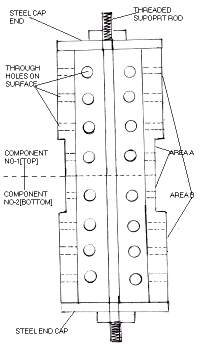
The components were fitted with steel end caps which was tightened on a threaded central rod as shown .
Drawing attached.
The sequence followed for plating was as follows-
1)The Internal bores of two components were masked with PVC based lacquer.
2)Two components were stacked on top of each other
3)The outer surface were cleaned with a solvent ,reverse etched in chromic acid solution and transferred to the Hard chrome plating bath for plating.
4)Based on the current density ,the plating time was adjusted to achieve 75microns of plating on all surfaces (stage I).
5)The components were removed from the plating bath ,rinsed and dismantled from the fixture. The masking compound was removed from the Bore, and the components were inserted in a furnace for baking at
200 °C for 4 hrs to prevent hydrogen embrittlement problems
6)The components were remasked with lacquer in the Bore and reassembled as before.
7)Area B of both components was covered with a combination of PVC sheets and adhesive tapes to prevent any further deposition. In doing so all holes on area B got blocked thus trapping air and chromic acid solution within the bore.
8)The components were inserted into the plating tank in such manner that the bottom component was entirely submerged in the solution, while 125mm of the upper component was submerged, since only area A' required further plating.
9)The usual sequence to achieve a good bonding of chromium on previously plated chromium surfaces was followed, and the current density was being gradually raised to its required value
10)During the above sequence ,a loud explosion occurred in the plating solution. The plating was immediately halted and the components were removed from the plating tank for inspection
11)It was observed that the plastic sheet on the top component had been ripped apart at some places
Our assessment of the cause of the above problem was one of the following:
a)Hydrogen evolving during HCP for the cathode had got ignited due to some spark or static charge -a phenomena observed occasionally while plating internal bores of small diameter.
B)Expansion of the air in the bore of the component due to the relatively high temperature of the plating solution(50-55 °C), May have caused the plastic to burst like a balloon.
12)Assuming 11-B to be the more likely cause we reapplied the PVC sheets and tapes on the components and kept some holes of the top component, which lay above the solution level uncovered to allow the inner air to escape after expansion.
13)The plating was then recommenced and continued for about 4 hrs to built up the required total thickness of 150 microns of hard chromium on area A'(stage II)
14)At the end of 4 hrs the component was inspected for coating thickness .This was found to be satisfactory and the components were dismantled from the fixture. After rinsing ,the masking compound was dissolved in the solvent.
15)Visual inspection after de-masking indicated that severe corrosion had taken place on the bore of the two components. Since corrosion on the top component was limited to the area that was dipped during stage 2 of the plating, it was clear that the phenomena had occurred during the second operation.
16)Visual inspection further showed the following results-
a)The corrosion had occurred even underneath the masking compound.
b)All the high current density areas on the ID, such as sharp edges of the grooves had got corroded more severely.
c)The maximum corrosion had occurred around the through holes present on the surface A and got reduced gradually away from the holes.
The above factors indicate an electrochemical rather than a chemical corrosion.
We had plated some other identical components from the same batch without any occurrence of a similar problem. Our assessment of the cause of the problem was as follows
a)The explosion at the commencement of stage II of HCP may have caused some loose contact to develop between the component and the cathode contact ,causing a voltage drop between the central threaded rod and the portion of the components dipped inside the solution.
We would like to know if this could have resulted in galvanic corrosion on the inner surfaces of the components.
b)We would like to know if the problem could have been enhanced by the blocking of holes ,on the surface which may have completely cut off the cathodic protection that was available to it during stage-I
c)Could the corrosion problem be related to the base metal composition?
The components being plated have following composition-:
PH-13-8 MO CF BAR STNLS XM-13
C: 0.03, MN: 0.020, P: 0.02, SI: 0.020, CR: 12.62, NI: 8.23 , MO:
2.170, CU 0.030,
AL: 1.080
d)As a precaution against a repeat of the above event ,we have changed the fixturing technique as follows-:
Two thick PVC bushed have been fitted on the end caps and the central rod is fitted on them so that it is disconnected from the electrical circuit in order to avoid any cell formation which may cause electrochemical corrosion to occur.
We would like you to evaluate our assessment of the problem and to confirm whether the corrective measures taken by us are proper .
We would also like to know about any other possible causes of the above problem and the necessary preventive measures
Thanks and Regards
Rajeev.D- India
2002
A. Hi Rajeev,
Picture for a moment if your end caps were made of plastic rather than metal, and your center rod still connected to the cathodic side of the rectifier, your anodes still connected to the anodic pole of the rectifier...
Your pipe would be "electrically floating"--connected to neither pole. What will then happen is that ionic current will still flow from the anodes to the cathode, but in two "halves": from the anodes to the OD of the pipe, and from the ID of the pipe to the center cathode rod. In this condition your pipe is "bipolar"--the OD is cathodic because it faces the anodes, the ID is anodic because it faces the cathode. It will etch terribly because it is actually an anode. Sounds like exactly what you described.
Personally I don't think warm air blew out the vinyl sheet though. I think it was hydrogen igniting, or at least being copiously generated.

Ted Mooney, P.E.
Striving to live Aloha
finishing.com - Pine Beach, New Jersey
Need quick confidential answers? $25
Need project assistance? $100/hr.
Sorry! Finishing.com is temporarily Read-Only.
Ted Mooney is retiring but I have several offers to take it over.
We're working hard to make sure we find it the best new home.