
| Search our quarter-million Q&As |
Home of the finishing HOTLINE since 1989
-----Ripple in Chrome Plating Rectifiers
What is the recommended limit for ripple in a chrome plating rectifier. This rectifier is used to apply engineering chrome.
George Tompsett- Hamilton Standard
1998
by Weiner & Walmsley
on Amazon (rarely)
or eBay (rarely)
or AbeBooks (rarely)
(affil link)
by Robert K. Guffie
on Amazon (pricey)
or eBay (sometimes)
or AbeBooks (rarely)
(affil link)
As a general rule the ripple in hard chromium plating should not exceed 5% -- lower is preferred.
When purchasing a rectifier, care should be exercised in specifying your requirement. For example you may have less than 5% ripple at 90% of the rectifiers output, however at 75% output, the ripple could be unacceptably high.
As a general rule, the rectifier should run at a minimum of 75% of rated output, even when operated at lowest output.
Trust this helps

Ken Lemke
Burlington, Ontario, Canada
Under 5% ripple has been the "standard" for years on engineering chrome.
James Watts- Navarre, Florida
1997
Maximum 5%.

Sara Michaeli
Tel-Aviv-Yafo, Israel
1997
1997
The responses from Ken, Jim, and Sara all came in at the same time before they got the chance to see each other's responses. Therefore, I would have to say that the answer is 5 percent 🙂
What is not quite a coincidence is the fact that if you take an incoming 3-phase supply, and full rectify it, you will get 5 percent ripple.

Ted Mooney, P.E.
Striving to live Aloha
finishing.com - Pine Beach, New Jersey
Need quick confidential answers? $25
Need project assistance? $100/hr.
I do not think that you will be under 5% with 3 phase without capacitors when you are loading the unit under half of the amperage of the unit. With proper cooling I prefer to run a power supply at 90% if nearly continuous and 95% if the time is short or intermittent.
A choke is set up for only one place in the load to suppress ripple. They work and are effective, but are not great where you have a large supply and are using it from minimum to maximum because of the variable load. Absolutely go to a 3 phase unit if you are going to do this.
James Watts- Navarre, Florida
1998
1997
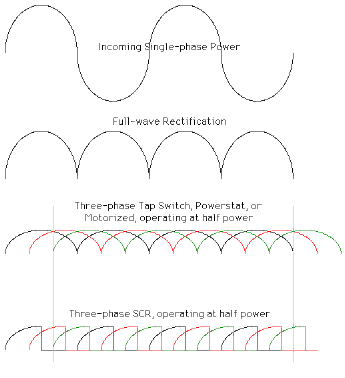
Incoming single-phase alternating current is in the form of a sine wave as shown in the first figure (I actually drew half ellipses because my CAD program doesn't draw sine waves).
If you full-wave rectify it, you get the second figure, 48 percent ripple.
With a three-phase power supply, the three-phases are deliberately set out of sync with each other, so that the low point of one phase coincides with near maximum points of the other two phases. The result is 5 percent ripple, as shown in the third figure. This figure applies to all types of three-phase rectifiers when they are operating at 100 percent output.
What happens at reduced output depends on the kind of rectifier. Tap switch and powerstat rectifiers actually adjust the transformer so that the wave shape remains the same and you get 5 percent ripple regardless of output voltage. But SCR rectifiers achieve reduced output by chopping off the power, giving you shark fins instead of camel humps; so at reduced output, SCR rectifiers have far more than 5 percent ripple--more like 30 percent.
Ted Mooney, P.E.
Striving to live Aloha
finishing.com - Pine Beach, New Jersey
Need quick confidential answers? $25
Need project assistance? $100/hr.
I do not know much about the ripple dampening needs in the chrome plating, but for many applications, 5% ripple is too large. Then filter circuits are commonly used in front of the rectifiers. These are simply capacitance-resistance combination with a feedback loop. Most power supplies come that way in electronics. I wonder if it costs too much to get these for electroplating. Could this solve the problem?
Mandar.
Mandar Sunthankar- Fort Collins, Colorado
1997
Filters (chokes) are available Mandar--that's what Jim is saying. But because we are speaking of very large output power, the costs can be substantial (in the several thousand dollar range).
Ted Mooney, P.E.
Striving to live Aloha
finishing.com - Pine Beach, New Jersey
Need quick confidential answers? $25
Need project assistance? $100/hr.
1997
In my own experience there are several problems with percent of ripple in plating circuits. But first a little history from plating design from fifty years ago. Then, twenty to fifty percent ripple was acceptable. Now five percent has been accepted for over twenty years as a standard. But no longer is it the rule. Due to the many new chemical formulations, especially those changed in order to be more environmentally friendly, the five percent rule is no more than a guideline. In fact the chemical companies themselves are in many cases specifying the ripple requirements. And while the five percent standard still persists in the field, many rectifiers are not able to meet the new requirements. So the actual process in todays' world should dictate what percentage of ripple is to be used. In the case of "chrome", it is one of the worst. For decorative chrome an absolute max of five percent is acceptable. For "hard chrome" the percent of ripple should be less. But generally speaking the industry standard is still five percent. Which means a normal rectifier "machine" direct from the factory without options will be five percent ripple.
To decrease the ripple all of what was said above by the other people applies. And to that I would like to add special phasing transformer machines. These use specially wound transformers to give a higher frequency AC output; then the output is rectified. Typically a rectifier uses six diodes wired as a double star configuration. But the special machines use from twenty-four to forty-eight diodes. The result is low ripple according to the designed need. These are usually used in conjunction with autotransformers for control purposes to avoid the above mentioned SCR problem of low utilization. In addition there are no further demands for chokes or capacitors. And of course these machines are usually three phase. Most businesses believe a rectifier is broken when it fails to produce a certain build-up given any amount of time. Please reconsider! A rectifier should be repaired, when it fails to produce a certain build-up in a certain amount of time. That is, when the electrical quality falls below the standard for that particular process. Diodes fail more often in six diode machines. But who checks this? One failed diode then often results in sub standard work that is difficult to trace. Check the percent of ripple on a periodic basis. If you do you may be surprised that you will catch so many problems, but you will also cure so many woes. StZ
Stephen ZabroskySecurance Electric
1998
You should check ripple at 10, 20, 30% etc to 100% capacity of the rectifier, right? Doesn't the % ripple change as the load changes?

Tom Pullizzi
Falls Township, Pennsylvania
1998
1998
The theoretical ripple of either a 6 phase star or three phase diametric with interphase transformer is below 5% when operating at their full output voltage.In plating rectifiers, these are the most common rectifier configurations. However, as one turns down the voltage through the use of either thyristors or saturable core reactors, the ripple increases to very high levels at the bottom end of the rectifiers voltage control range, i.e. a 12 v.d.c. rectifier running at 3.0 volts d.c. may exhibit ripple as high as 50% or greater. A chromium plating tank acts somewhat like a capacitor and should one measure ripple when connected across a load in a chromium plating tank one would tend to see less ripple than if the rectifier were connected across a resistive load bank. In the early fifties, it was thought that the only type of rectifier that would work on chromium was a tap switch machine where we do not get any phase shifting and as a result tend to maintain the same percent ripple across the full voltage control range of the rectifier. I have seen three phase half wave tap switch controlled rectifiers exhibit problems in chromium plating (their theoretical ripple is 18.3%)whereas a phased back saturable core reactor controlled rectifier did not, this indicated to me that it was more of a wave shape problem than one of ripple per se. Obviously filters on the output side of the rectifier help(either capacitive or reactive or a combination of both).
To summarize, ripple in the output of a rectifier used to chromium plate can certainly be a problem but is not always but I do believe that it narrows down your operating window.Most rectifiers that are produced today WILL NOT give you less than 5% ripple at less than their rated output voltage. I would generally prefer to supply a rectifier for use on chromium that was to be used at 75% of it's rated output voltage but have seen many 12 volt machines operating below 6 v.d.c. without problems.
John NeedhamOur Chrome Rectifier is of 7000 Amps capacity at a voltage of 10 to 15 V, depending on the load. Is it okay if we operate the rectifier at 4000 Amps ? If not how do we overcome the problem of having to use the rectifier at 4000 Amps even if the rectifier is rated for 7000 Amps ? How do we check if the rectifier is functioning effectively?
Thanks
Ravi Sailesh- Vizag, Andhra Pradesh, India
2000
What effect does the ripple in either the voltage or current have on finished product?
Michael Ewingchrome plating - Melbourne, Australia
2005
By Ohm's Law, current equals voltage divided by resistance. Since the resistance is fixed for a specific load of ware being plated, in a plating application ripple in current and ripple in voltage are actually the same thing. The biggest consequence of excessive ripple in chrome plating is probably the possibility of deactivating the chrome and getting laminar plating.
Ted Mooney, P.E.
Striving to live Aloha
finishing.com - Pine Beach, New Jersey
Need quick confidential answers? $25
Need project assistance? $100/hr.
2005
WE ARE USING LOT OF PLATING RECTIFIERS. I WANT TO KNOW HOW TO CALIBRATE D.C.CT AND D.C.SHUNT? IT HAS BEEN OBSERVED THAT THE D.C.CTs AND SHUNTs ARE GIVING WRONG SIGNAL AND CORRESPONDING AMMETER READING WILL BE WRONG. WHAT TYPES OF METERS ARE AVAILABLE TO CALIBRATE THIS?
MANOJKUMAR KULKARNI- Bangalore, INDIA
2005
2005
It is not possible to run huge currents through a small meter; so a calibrated resistance, called a shunt, is placed in the circuit, and the voltage drop across that calibrated resistance is measured. According to Ohm's Law, if the resistance is known, and you measure the voltage, you can calculate the current.
Most shunts are 50 mV shunts. That means that if the rectifier is operating at full rated current, there will be a drop of 50 mV across the shunt. And that implies that most ammeters are 50 mV as well. Shunts may suffer bad connections, but it is unlikely that the resistance of a block of copper will change.
So a starting point would be make sure that the meters read full amperage if a voltage of 50 mV is placed across them. Then install those meters. Maybe someone misunderstood how the systems work are started putting old shunts on differently sized rectifiers? That must be corrected.
Ted Mooney, P.E.
Striving to live Aloha
finishing.com - Pine Beach, New Jersey
Need quick confidential answers? $25
Need project assistance? $100/hr.
Chrome applications at lower than full voltage-current with six phase thyristor control rectifiers typically use choke filtering to minimise 300 Hz ripple below 5% down to nominal 50% load level. Below nominal 50% load, and/or for lower ripple than 5%, the addition of capacitor along with choke (LC) filtering is effective solution to reduce ripple well below 1%. Capacitor is switched out during reverse operation as capacitor is typically polarity sensitive electrolytic type.
Tim Robbins, M.Sc.- Melbourne, Victoria, Australia
2006
2007
How can ripple be measured.
We have a single phase SCR controlled unit. We are using a Digital multimeter to give us the min & max (while set on DC) & calculating the % ripple As Emin - Emax / Eavg.
Is this correct?
We are getting values that are too low (1-3%) for 1-phase SCR units running at 25% of current rating.
- Dubai, UAE
Sorry! Finishing.com is temporarily Read-Only.
Ted Mooney is retiring but I have several offers to take it over.
We're working hard to make sure we find it the best new home.