Curated with aloha by
Ted Mooney, P.E. RET

Home of the 'finishing HOTLINE' since 1989
OUR ON-LINE REFERENCE MATERIALS
- Anodizing

Where Do "White Spots" Come From?
by Robert Probert.
Why Are My Aluminum Cathodes Red?
by Nosti, Ciejka, & Gilbert.Drew
NostiASF Anodizing vs. Voltage,

Welding vs. Bolting of Aluminum Cathodes
by Drew Nosti
Let's Talk Cathodes
by Drew Nosti- Coloring of Metals
Goran
BudijaCollection of formulas for chemical, electrochemical & heat colouring,
cyanide-free immersion plating and electroplating (2025).- Corrosion

Why Apply a Coating? -- Corrosion,
by Mario S. Pennisi
- Electroforming

Understanding, Measuring and Controlling Stress in Electroformed Metals,
by Berl Stein, CEF
- Electroplating for Electronics
Paul
Stransky• Flux Basics
• Nickel Diffusion Barriers
• Copper Plating of High-Aspect-Ratio Plated-Through-HolesRudy
Sedlak• Ammoniacal Etching of Copper
• Resist Lifting in Gold Plating
- Electroplating (Commercial)
-

Plating on Aluminum [in Swedish],
by Anders Sundman
Introduction to Barrel Plating,
by Frank R. Zemo
Chrome Control,
by Geoffrey P. Whitelaw
Chrome Plating [in Swedish],
by Anders Sundman
Crib sheet for plating,
A periodic table for plating, electrochemical equivalents, troubleshooting nuggets, other little used facts.
by Thomas J. Pullizzi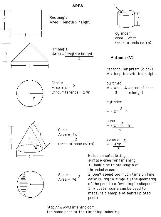
Formulae of surface areas and volumes of simple shapes,
May we strongly recommend that you calculate the surface area of everything you finish.
by Thomas J. Pullizzi
Improving your Chloride Zinc Plating Operation,
by Stephen Schneider.
Troubleshooting Modern Bright Nickel Plating Solutions,
by Thomas J. Pullizzi.
Nickel Plating [in Swedish],
by Anders Sundman
- Environment & Safety

Chart of pH vs. Residual Concentration of Metals Rudy
Sedlak• What Chelates Are and Why We Use Them
• Modern Liquid Cleaners
• Dry Acid SaltsMike
McDonaldLiquid Cleaners vs. Dry ... the choice is easy
- Hot-Dip Galvanizing
-
Dr. Thomas
H. Cook• Dynamic Flux Tests for Hot-Dip Galvanizing.
• Lower Zinc in Hot-Dip Galvanizing.
• ACNV Test - Metals
-
Metallic Materials [in Swedish],
by Anders Sundman - Nostalgia
-

Illustrated trouble-shooting guide in rhyme from 1955.

Proceedings of the American Electroplater's Society, 1960 
Everyone knows Wiss scissors, shears, etc. Don Wiss has collected incredible memories of J. Wiss & Sons Co from 1848-1976 (external website)
- Painting & Powder Coating
-
Ron
Joseph• Maintaining Brightness in Spray Booths
• Keeping an HVLP Spray Gun in Compliance with Regulations
• Transfer EfficiencyKen Green Spraybooth Problems: Air, Filters, Exhaust Mario S. Pennisi Powder Coating -- an introduction by Mario S. Pennisi. - Passivation of Stainless Steel
-

Effective Methods for the Testing of Stainless Steel Passivation
by Wolf Koslow
Passi-pipe Explorer
by Wolf Koslow - Pickling
-

Chart of pickling time and baumé as a function of acid concentration and iron content
by Barlow Campano, Hidada Co. Ltd., Kingdom of Saudi Arabia.
"The Kleingarn Regenerated Spent Acid at Increasing Ferrous (Fe+2) and Ferric (Fe+3) Chloride Content"
by Barlow Campano, Hidada Co. Ltd., Kingdom of Saudi Arabia.
Ammonium Bifluoride Equivalency to Hydrofluoric Acid in the Presence of Strong Acids for Metal Pretreatment
by John Barrows, MSF Goad Co., Independence, MO.
- Plant & Process Engineering/Construction
-

• Plating Shops for the New Millennium, a design guide by Ted Mooney.
• 20 Ways to Cut Water Usage in Plating Shops, some tips from Ted Mooney.
• Hard Chrome Plating - Materials to consider, by Freeman Newton.
• Please Don't Leak on the Job - A guide to cementing PVC Pipe, by Freeman Newton. - Pretreatment
-
Pretreatment & Activation [in Swedish],
by Anders Sundman
The Pretreatment Trouble Shooter
by Dave Wright [deceased], in Finishing Touch Newsletter, courtesy of CCAI.
Cleaning & Rinsing for Powder Coating
by Bob Utech - Replacement Technologies
 A possible alternative to Nickel or Chrome plating, the Kolene salt bath quench/polish/quench process.
Closing the Quality Gap on Textured Molds: High Quality Surface Finishes Make the Difference, and Equation for Efficiency: FF + f/P Nearly Eliminates the Need for Polishing --two articles by Midwest Mold and Texture Corporation.
End of Life (Vehicles) European Directive (English language) posted 11/29/00.
- Stripping
 Geoffrey Whitelaw gives us the full procedure and data for economical stripping of gold
Rudy Sedlak tells us about Stripping Resists … and the hell involved in Stripping Tin and Solder from small holes on thick boards.
Geoffrey Whitelaw gives us the full procedure and data for economical stripping of gold
Rudy Sedlak tells us about Stripping Resists … and the hell involved in Stripping Tin and Solder from small holes on thick boards.
- Titanium
-

Titanium - Why Coat It?
by Milt Stevenson, Jr., Anoplate
OLD PAGES NEVER DIE, THEY JUST FADE AWAY
Looking for an article you remember seeing here, but which gave up it's front page position to make way for newer items, here it is:
![]() Interview with a Vampire--a conversation (out of whole cloth) between an ISO9000 auditor and a client.
Interview with a Vampire--a conversation (out of whole cloth) between an ISO9000 auditor and a client.
![]() An open letter from University of Baltimore's Merrick School of Business regarding new technology of
divalent chromates.
An open letter from University of Baltimore's Merrick School of Business regarding new technology of
divalent chromates.
![]() CFR438, the proposed Metal Products and Machinery Effluent Guidelines, are serious business for all finishers. Read an
Open Letter from the Aluminum Anodizers Council and James N. McClatchey's statement to the EPA from the public hearing of June 28, 1996. (McClatchey is V.P. and Production Manager of Southern Aluminum Finishing Co.)
CFR438, the proposed Metal Products and Machinery Effluent Guidelines, are serious business for all finishers. Read an
Open Letter from the Aluminum Anodizers Council and James N. McClatchey's statement to the EPA from the public hearing of June 28, 1996. (McClatchey is V.P. and Production Manager of Southern Aluminum Finishing Co.)